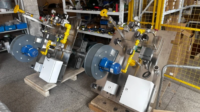
An industrial burner is only one part of an industrial heating system. Fuel must reach it at a suitable pressure; combustion air must match the firing demand; and controls must establish the required conditions before fuel is admitted. An industrial combustion system therefore has to be engineered and checked as an integrated package. A U.S. Department of Energy project description, for example, identifies fuel sensing, air and fuel flow devices, and industrial burners as connected parts of one combustion system.[1]
What does industrial combustion system assembly include?
Combustion system integration begins with the operating basis: fuel composition and supply pressure, required heat input, process temperature, turndown, airflow, available electrical power, and the equipment being heated. Engineers then define the physical and control interfaces among the industrial burner system, industrial fuel train, air supply, and burner control panel. HEATFLAM describes this scope in its industrial combustion solutions overview.
HEATFLAM assembly video. Watch on YouTube if the player does not load.
How is the fuel train assembled around the burner?
Fuel train assembly translates the piping and instrumentation design into an accessible physical arrangement. Depending on the approved design, a gas train system includes isolation, filtration, pressure regulation, pressure indication or switching, and automatic shutoff and flow-control devices. The order, ratings, venting, and number of devices must follow the actual fuel, equipment, and applicable requirements. The HEATFLAM fuel train and skid range shows the type of equipment category discussed here.
The reason to document each interface is practical: a regulator selected without the expected inlet range, a valve without the required flow capacity, or a pressure tap in the wrong location changes how the package behaves. As a narrow regulatory example, the U.S. OSHA rule for bakery ovens addresses gas-tight piping, safety shutoff valves, blower interlocks, and regulators in specified circumstances. That bakery rule is an example of application-specific requirements, not a universal design checklist for all industrial burners.[2]
Where do gas pressure controls and interlocks fit?
Pressure monitoring connects the industrial gas control system to the burner safety logic. A low-pressure or high-pressure condition must be interpreted against the project’s approved operating range and control sequence. As one component example, Honeywell lists its C6097 gas pressure switch family for gas and air pressure monitoring, including low- and high-gas-pressure protection applications. That product description explains a possible device role; it does not establish that a C6097 is installed in every HEATFLAM package.[3]
For procurement, request a marked piping diagram and an interlock matrix. These should identify what each pressure switch monitors, which condition permits ignition, and which fault commands fuel shutoff. Check the selected switch model, pressure range, connection, and setpoint against the design documents before acceptance.
How do actuators and combustion controls work together?
An actuator positions an air damper or fuel-control element in response to the control strategy. Siemens documents its SQM4 family for air and gas dampers and for load-dependent control of gas, oil, or combustion-air flow. The actuator, linkage, valve or damper, feedback, and burner controller must be matched as a system; an actuator’s brand alone says nothing about the finished firing curve.[4]
The U.S. Department of Energy advises checking and setting burner air-to-fuel ratios against measured operating conditions. Excess air requirements change with the burner and process; moisture- or solvent-evaporating equipment has additional airflow considerations. For this reason, a combustion control system should be specified with its required load range, feedback signals, and field tuning plan, rather than described only as “automatic.”[5] See HEATFLAM’s electronic ratio combustion control category for a related system type.
What should the burner control panel integrate?
The burner control panel is where field devices, operator commands, fault indications, and the burner management sequence meet. Its drawings should make the relationship between power, ignition, flame supervision, pressure permissives, airflow permissives, actuators, and shutoff valves legible. Each signal needs a defined state on startup, normal running, and fault shutdown. The panel’s enclosure, electrical rating, interfaces, and applicable code depend on the installation site.
A useful design review traces one fault from sensor to final action. For example, when a required combustion-air permissive is lost, the reviewer should be able to identify the input, the controller response, the fuel shutoff action, and the reset condition in the approved sequence. OSHA’s bakery-oven rule explicitly requires a blower-to-shutoff-valve interlock for the covered equipment; other applications require their own code and hazard review.[2]
What should buyers check before installation and commissioning?
Factory assembly and site commissioning answer different questions. Assembly establishes the physical package and documented connections. Site work verifies the installed fuel supply, ventilation, electrical interfaces, process conditions, control sequence, and actual combustion behavior. A factory view of an industrial burner assembly therefore cannot prove the final installation’s settings or compliance.
| Review item | What to request |
|---|---|
| Fuel train | Piping diagram, component list, ratings, and inspection or test records specified for the project. |
| Controls | Electrical drawings, I/O list, cause-and-effect or interlock matrix, and approved sequence. |
| Site integration | Connection requirements, applicable code basis, and a commissioning responsibility and test plan. |
HEATFLAM’s combustion project gallery illustrates several installation formats. Use it to discuss layout and interfaces, then request documentation for the exact configuration under review.
What information starts a custom combustion system review?
For a useful technical proposal, provide the application and heated equipment, fuel type and composition, available inlet pressure, required heat input and operating range, process temperature, combustion-air conditions, supply voltage, control interface, emissions or permit requirements, and installation location. Include existing drawings and burner or valve model numbers for a retrofit. These inputs let combustion engineering teams define the fuel and combustion control scope before selecting components.
Frequently Asked Questions
Send your fuel, heat input, process conditions, site location, and control requirements so HEATFLAM can review a suitable assembly and integration scope.
REFERENCES AND DATA SOURCES:
- U.S. Department of Energy — CX-031121: Omnivore Combustion System (Published 2024-06-07).
- U.S. Occupational Safety and Health Administration — 29 CFR 1910.263, Bakery Equipment (Accessed 2026-10-08).
- Honeywell — C6097 Pressure Switches for Gas (Accessed 2026-10-08).
- Siemens — Actuator SQM40/SQM41, Data Sheet CC1N7817en (Published 2024-12-06).
- U.S. Department of Energy and Industrial Heating Equipment Association — Improving Process Heating System Performance: A Sourcebook for Industry, Second Edition, Appendix B, Tip Sheet 2 (Tip sheet published 2007-11).
