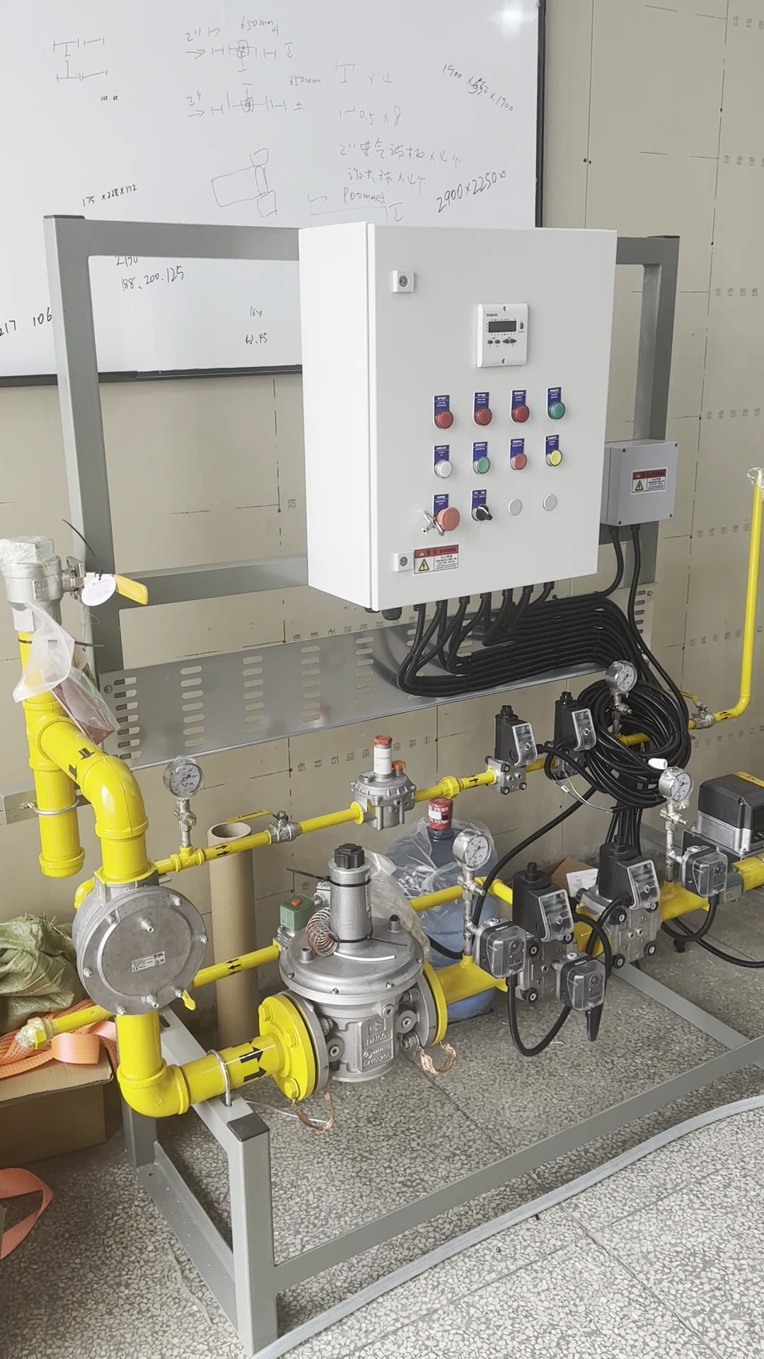
An RTO combustion system must be specified around the oxidizer’s operating duty and fuel supply. For this project, HEATFLAM integrated a natural-gas burner system, fuel train, piping, and a control panel for a customer-specific RTO application. The video and close-up photographs show the equipment assembly and its major interfaces.
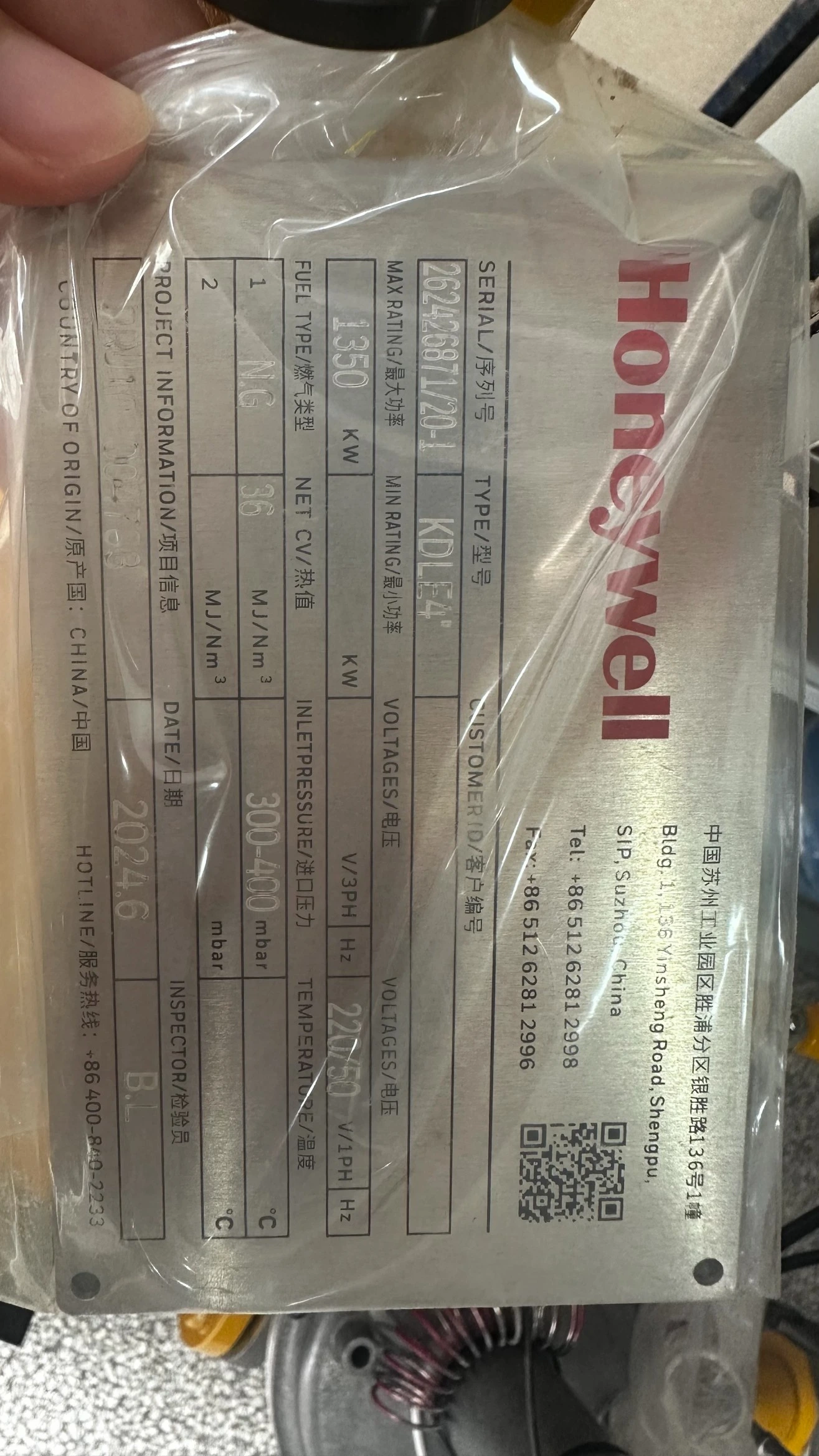
What does the 1,350 kW rating describe?
The 1,350 kW figure is the maximum rating stated on the burner nameplate. It is not the RTO’s exhaust-gas throughput, VOC removal efficiency, heat-recovery efficiency, or measured site fuel consumption. The same nameplate identifies natural gas as the fuel, 300–400 mbar as the inlet-pressure range, and 36 MJ/Nm³ as Net CV. These values define the documented equipment configuration; actual site supply conditions still need to be checked during integration.
| Nameplate field | Documented value | Selection meaning |
|---|---|---|
| Maximum rating | 1,350 kW | Burner nameplate capacity, not RTO treatment capacity |
| Fuel type | Natural gas | Fuel used for this configuration |
| Inlet pressure | 300–400 mbar | Declared burner-inlet range to verify against the delivered gas supply |
| Net CV | 36 MJ/Nm³ | Nameplate fuel-heating-value basis |
How does this combustion package fit into an RTO?
A regenerative thermal oxidizer moves process exhaust through heat-storage media and a combustion zone. Auxiliary fuel supports the required thermal conditions when recovered heat and the process stream alone do not provide enough heat. The U.S. EPA’s oxidizer design chapter describes that operating principle. This HEATFLAM package supplies and controls natural gas for the burner side of that application; the images do not depict an entire RTO vessel, media bed, exhaust fan, or stack.
The practical integration question is whether the burner, gas valve train, and combustion control system match the RTO’s start-up sequence, temperature-control strategy, available fuel pressure, and protective interlocks. HEATFLAM’s exhaust-gas-treatment solution overview describes the broader application context.
What is visible in the natural-gas fuel train?
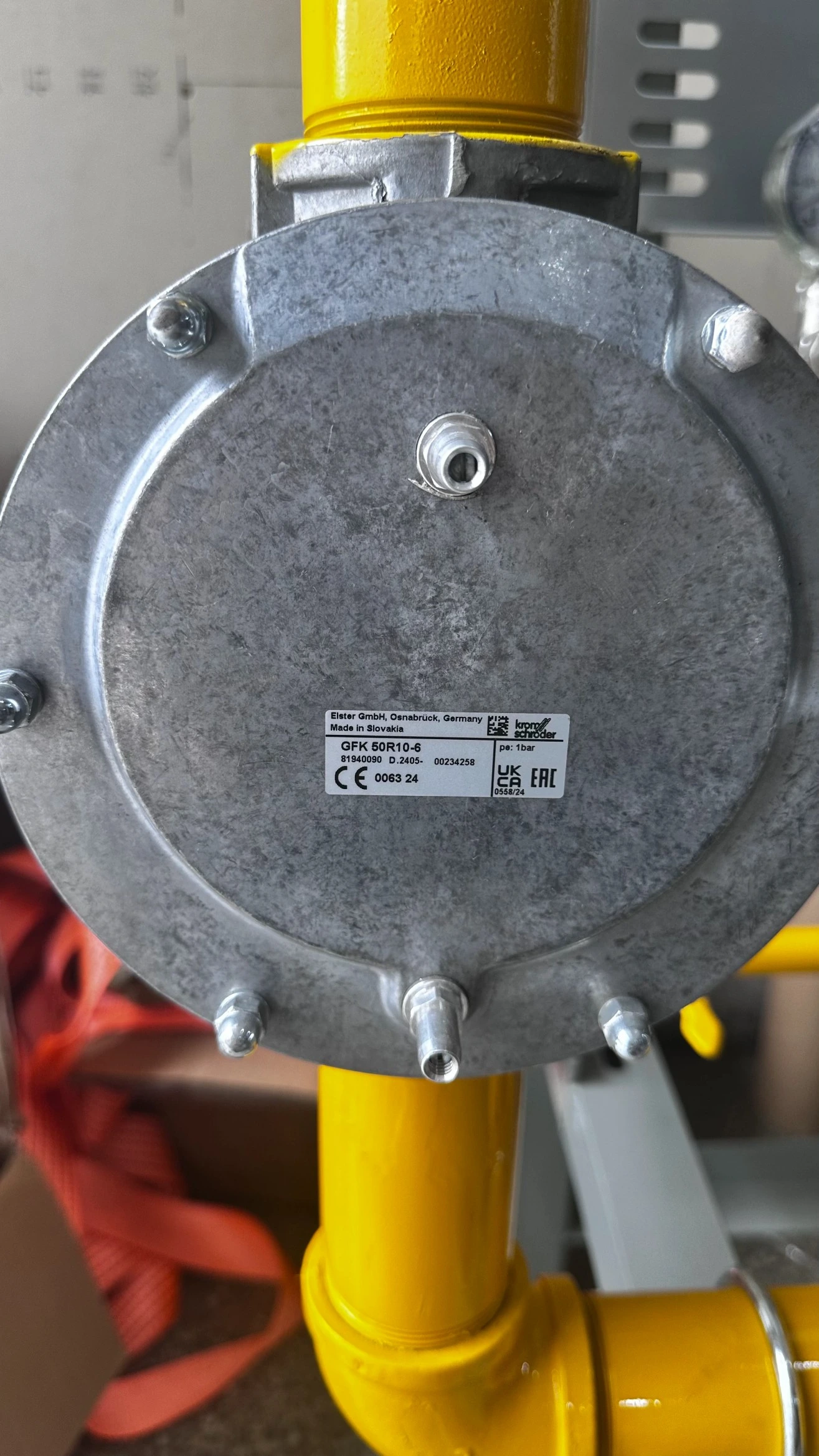
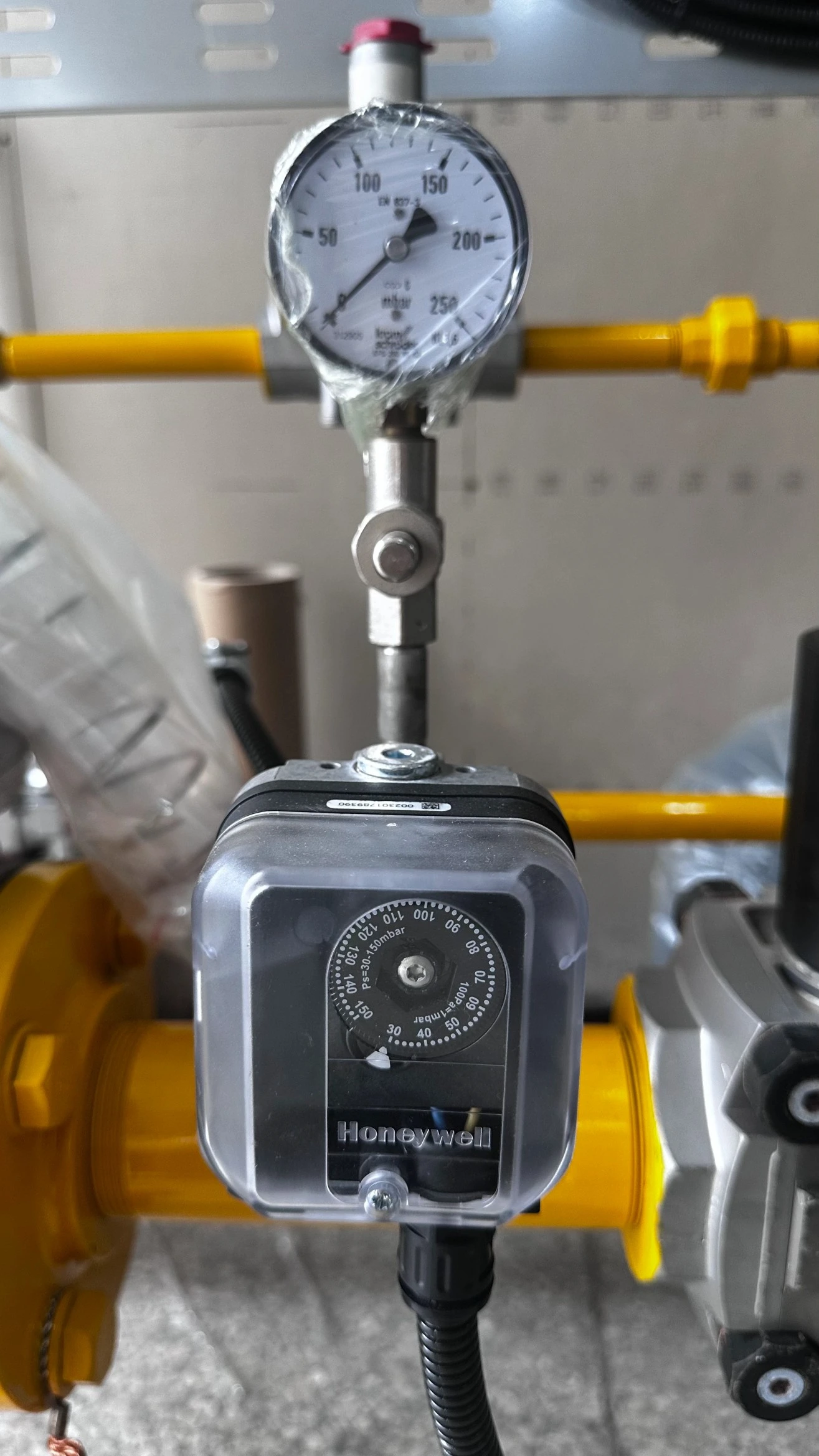
The project media show a piped industrial gas train with pressure-regulation hardware, valve assemblies, pressure instruments, and an integrated control cabinet. In a custom RTO combustion package, these elements must be treated as one fuel-delivery and protection chain rather than as independent catalogue items. Filtration, regulation, shutoff, monitoring, and flow-control functions need to be matched to the specified gas quality, pressure range, firing duty, and control sequence.
A fuel-train review should identify the location and rating of each component, pressure loss at maximum demand, the protective shutdown sequence, and access for inspection. For related engineered assemblies, see HEATFLAM’s fuel-train and skid systems.
What does the burner control panel show?
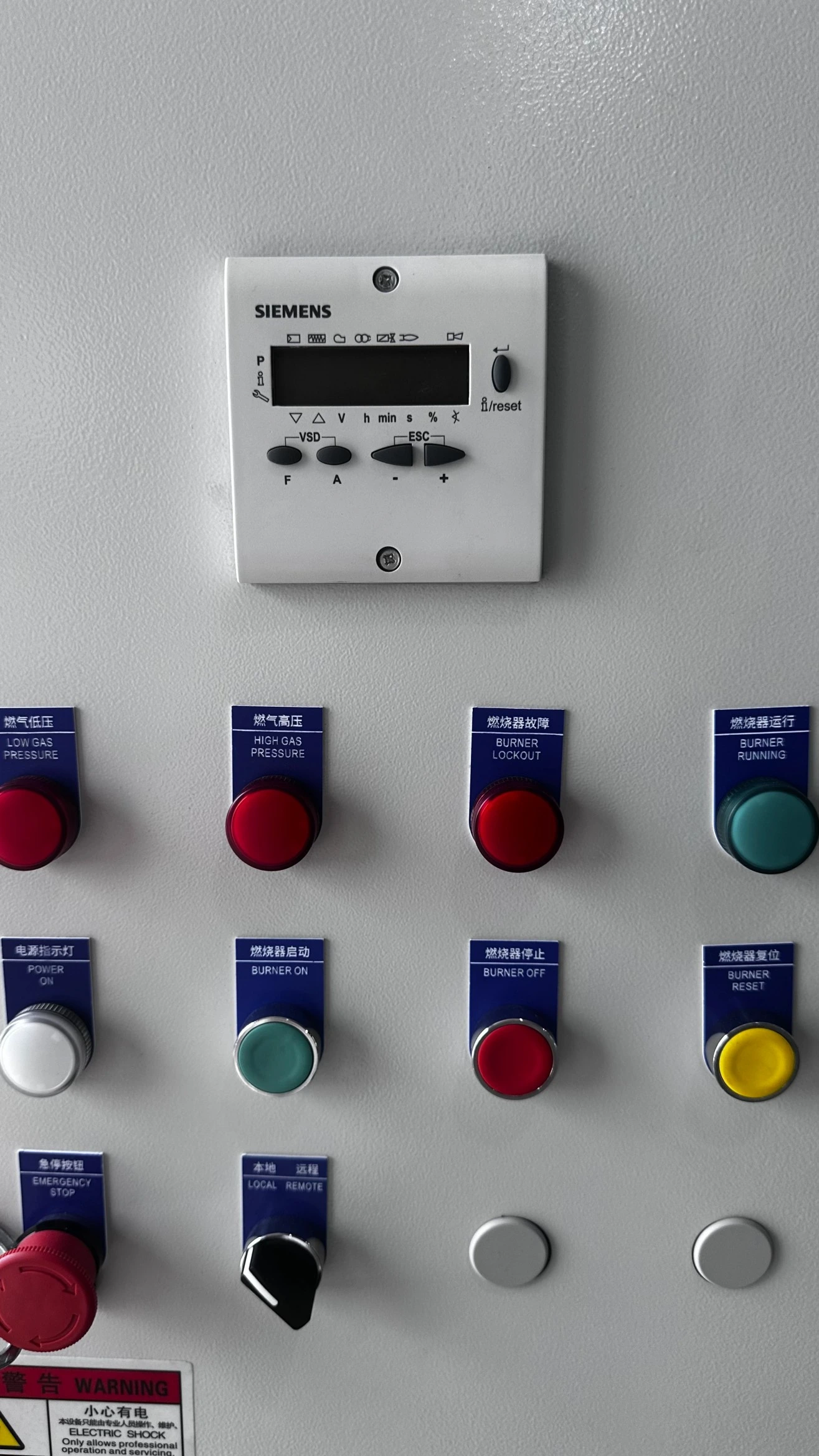
The photographed panel has labeled indications or controls for low gas pressure, high gas pressure, burner lockout, burner running, burner on/off, burner reset, and local/remote selection. These visible functions help operators identify burner status and initiate the intended local actions. The photographs alone do not establish the complete control logic, alarm setpoints, or tested interlock sequence.
The U.S. EPA’s thermal-oxidizer monitoring guidance identifies outlet VOC concentration and combustion-chamber temperature as primary performance indicators for VOC control, with auxiliary-fuel-line pressure among other indicators. A burner control panel supports operation; it does not by itself document the RTO’s treatment performance.
Which inputs are needed to specify a comparable system?
A 1,350 kW nameplate figure does not define a new project by itself. Specify the maximum and minimum burner duty, natural-gas composition or declared heating-value basis, minimum and maximum available inlet pressure, required firing/control mode, electrical supply, RTO interface signals, start-up and shutdown philosophy, and site operating conditions. Include the RTO supplier’s drawings and control narrative where available.
The U.S. Department of Energy’s process-heating sourcebook explains why air-to-fuel control must be set for the actual fuel, burner, and process conditions. That general engineering principle supports reviewing the complete natural-gas combustion system instead of choosing equipment from nominal capacity alone. HEATFLAM’s exhaust-gas-incineration burner category provides a related product starting point; final model suitability requires project-specific verification.
Frequently Asked Questions
Share your RTO duty, fuel data, gas-pressure range, burner-control requirements, and drawings for an engineering review.
REFERENCES AND DATA SOURCES:
- U.S. Environmental Protection Agency — Air Pollution Control Cost Manual, Chapter 2: Incinerators and Oxidizers (accessed 2026-09-24).
- U.S. Environmental Protection Agency — Monitoring by Control Technique: Thermal Oxidizer (accessed 2026-09-24).
- U.S. Department of Energy — Improving Process Heating System Performance: A Sourcebook for Industry, Second Edition (accessed 2026-09-24).
- International Organization for Standardization — ISO 13577-2:2023, Combustion and Fuel Handling Systems (published 2023-12).
