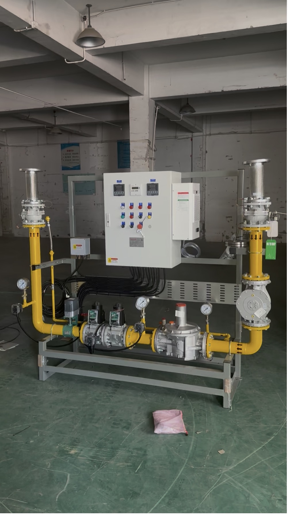
What Is a Gas Valve Train for an Industrial Burner?
A gas valve train for an industrial burner is the piping, valves, instruments, and control interfaces that deliver gas to a burner at controlled pressure and flow while supporting the burner management system’s safety sequence. It is not simply a set of valves: the components must be sized and arranged as one system around the burner, process, fuel supply, and applicable local requirements.
For a boiler, furnace, kiln, dryer, oven, thermal oxidizer, or hot-air system, the correct burner gas train should be confirmed together with the burner duty and combustion controls. Heatflam supports customized combustion-system integration based on project operating conditions.
Which Components Are Included in a Burner Gas Train?
The final arrangement varies by fuel, capacity, risk assessment, and jurisdiction. A typical industrial burner gas train may include:
- Manual isolation valve: isolates the fuel supply for service and maintenance.
- Gas filter or strainer: helps protect downstream valves and regulators from debris.
- Gas pressure regulator: reduces and stabilizes pressure for the burner’s required operating range.
- Pressure gauges and test points: support commissioning, troubleshooting, and service checks.
- Gas pressure switches: provide low- and/or high-pressure permissives or shutdown inputs, according to the approved control design.
- Safety shutoff valves: normally closed automatic valves that stop fuel flow on a safety trip or loss of the required safety signal.
- Control valve or ratio-control element: modulates gas flow when the burner uses high/low, modulating, mechanical-linkage, pneumatic, or electronic fuel-air control.
- Valve-proving arrangement: where required, checks the integrity of shutoff valves before or during the prescribed burner sequence.
| Component | Primary selection input |
|---|---|
| Gas pressure regulator | Fuel type, inlet-pressure range, outlet-pressure setpoint, required flow, and allowable pressure drop. |
| Safety shutoff valve | Fuel, pressure, flow, voltage, closing function, approvals, and burner-management logic. |
| Pressure switch | Required setpoints, pressure range, electrical interface, enclosure/environment, and control sequence. |
| Piping and connections | Flow capacity, pressure rating, layout, connection standard, service access, and project code. |
How Do Safety Shutoff Valves and Pressure Switches Protect the Burner?
The burner management system uses defined permissives and trip signals to control the ignition and fuel sequence. Gas pressure switches can indicate whether supply pressure is within the approved operating window. When a safety condition is not satisfied, the control system should prevent startup or command fuel isolation in accordance with the approved sequence.
Safety shutoff valves are selected for their intended fuel service, pressure, capacity, electrical specification, response characteristics, and applicable approvals. The number of valves, use of proof-of-closure or valve-proving functions, venting approach, and safety logic must be determined by the system design—not copied from another burner size or application.
How Should You Size a Gas Pressure Regulator and Valve Train?
Start with the burner’s maximum fuel input and the actual properties of the gas supplied at site. A regulator or valve selected only by nominal pipe size can create inadequate flow, excessive pressure loss, unstable regulation, or poor turndown performance. The calculation should account for available inlet pressure, required outlet pressure, gas composition, maximum and minimum flow, pressure drop through upstream devices, and the selected connection arrangement.
Natural gas, LPG, mixed gas, biogas, hydrogen-containing fuels, and other gases do not share the same operating assumptions. Confirm fuel composition and pressure conditions before selecting any gas pressure regulator, solenoid valve, or burner gas train.
Which Control Requirements Change the Gas Train Design?
A burner gas train is selected together with its control strategy. On/off and high/low burners may use a different control arrangement from fully modulating systems. Electronic fuel-air ratio control, VFD combustion-air control, PLC or BMS communication, remote alarm requirements, and redundant safety functions can all affect the valve-train specification and control cabinet interface.
For replacement work, do not assume a new component is interchangeable merely because its connection size or apparent function is similar. Confirm the existing model, pressure range, electrical supply, safety function, installation layout, and approved burner control logic.
What Information Should You Send for a Gas Valve Train Quote?
A clear inquiry lets the engineering team evaluate the gas train as part of the combustion system rather than offer an unsuitable standard assembly. Please provide:
- Fuel type and, where available, gas composition or heating value.
- Required heat output and burner make/model, if already selected.
- Process temperature and application, such as boiler, furnace, kiln, dryer, oven, or thermal oxidizer.
- Minimum and maximum inlet pressure, required outlet pressure, and available pipe connection details.
- Site conditions: indoor/outdoor installation, ambient temperature, hazardous-area classification, altitude, space limitations, and local code requirements.
- Control requirements: on/off, high/low, modulating, PLC/BMS interface, voltage, and required alarms or interlocks.
Frequently Asked Questions
Send your fuel type, heat output, process temperature, application, site conditions, inlet/outlet pressure, and control requirements. Heatflam can review the information for a customized burner gas train proposal.
REFERENCES AND DATA SOURCES:
- ISO 23550:2018, Safety and control devices for gas and/or oil burners and appliances — General requirements. Status should be checked before use in a project specification.
- ISO 23551-1:2024, particular requirements for automatic and semi-automatic shut-off valves.
- NFPA 86 (2023), Standard for Ovens and Furnaces; applicability depends on the installation and jurisdiction.
