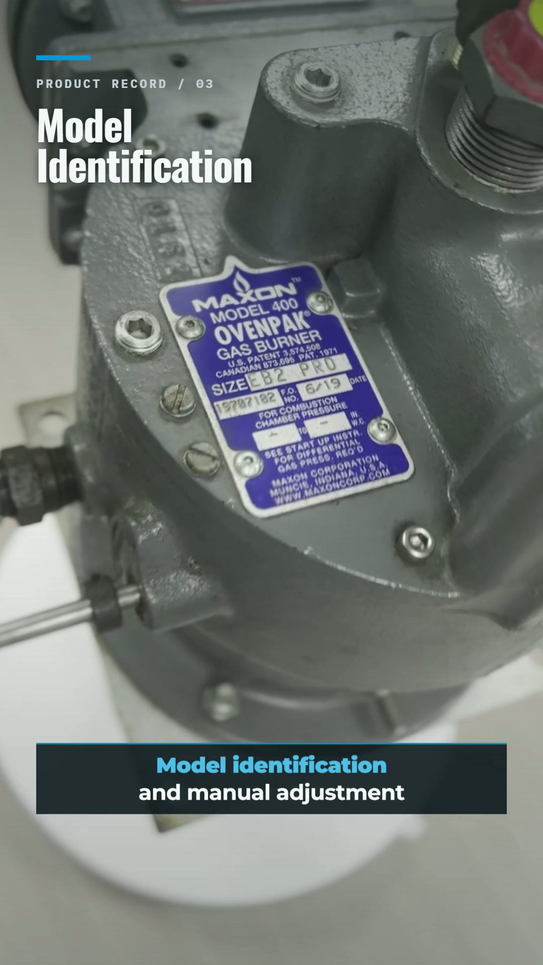
When an industrial burner needs replacement, the visible model name is only the beginning. A correct selection must match the process duty, fuel and combustion-air conditions, physical interface, control method, safety system, and site standards. This guide explains how to assess a MAXON OVENPAK 400 EB2 PRO gas burner from its structure and nameplate, what the manual adjustment mechanism and mechanical burner linkage demonstrate, and which information procurement and engineering teams should prepare before ordering a replacement.
What Is the MAXON OVENPAK 400 Gas Burner?
Honeywell identifies the MAXON OVENPAK® 400 as a nozzle-mixing gas burner family for industrial direct-fired applications. The manufacturer lists ovens, dryers, paint-finishing lines, paper and textile machinery, food-baking ovens, coffee roasters, grain dryers, and fume-incineration duties among typical applications. These examples describe the product family; they do not confirm that one EB2 configuration is suitable for every oven gas burner, dryer gas burner, or industrial air-heating project.
The official product information distinguishes integral-blower arrangements from EB external-blower versions. In an external blower gas burner configuration, combustion air is provided by a separate air source rather than an integral burner blower. This distinction affects the air connection, available pressure and flow, control integration, installation layout, and the data required for replacement selection.
How Should the EB2 PRO Model Marking Be Read?
The blue nameplate on the demonstration unit is the first evidence for burner model identification. It connects the physical equipment to the OVENPAK family and the EB2 PRO marking visible on the unit. For procurement, however, a typed model description is less reliable than a clear, straight-on photograph of the complete nameplate. Small suffixes, assembly identifiers, electrical information, or configuration marks can materially affect the supplied burner.
| Visible or recorded item | What it helps confirm | What must not be assumed |
|---|---|---|
| MAXON OVENPAK® 400 | Product family and manufacturer branding | Exact capacity or complete assembly |
| EB2 PRO marking | A model/configuration reference for further checking | Drop-in interchangeability with another EB2 unit |
| Manual handle and linkage | Mechanical control arrangement and direction of movement | Correct air-fuel ratio, calibration, or tested operation |
| Connection and mounting photos | Orientation, available space, and interface review | Final flange, piping, or wiring compatibility without measurements |
Which Structural Features Matter During Inspection?
A useful structural review should document the complete industrial gas burner rather than focus only on cosmetic condition. For an OVENPAK EB2 burner, buyers and maintenance teams should record the following visible areas:
- Burner body and mounting interface: Photograph the complete body, mounting face, orientation, bolt pattern, discharge-side arrangement, and surrounding clearances.
- External combustion-air connection: Record flange or adapter dimensions, required air direction, available blower data, and the pressure-measurement locations used by the existing system.
- Fuel connection: Confirm fuel type, connection size and standard, orientation, upstream gas-train arrangement, regulated pressure, and available differential pressure.
- Manual adjustment mechanism: Record handle travel, stops, locking method, shaft direction, and any position indication without changing the established setting during identification.
- Mechanical linkage: Photograph link arms, pivots, fasteners, lever orientation, and the connected shafts at both ends of travel where safe and authorized.
- Ignition and flame-supervision interfaces: Record the installed ignition, pilot, flame detector, cable routing, and burner-management connections rather than assuming the new unit uses the same arrangement.
These records allow a supplier to compare mechanical and functional interfaces. They do not replace the manufacturer’s installation instructions, combustion calculations, site risk assessment, or commissioning procedure.
What Do the Manual Handle and Mechanical Linkage Demonstrate?
The demonstration footage shows the manual handle moving and the linked mechanism responding at the same time. This is useful because it makes the mechanical relationship visible: movement at the control handle is transferred through the linkage to the connected control shaft or shafts. For engineers, the motion provides a reference for linkage geometry, travel direction, pivot positions, and accessible adjustment points.
The movement alone does not confirm the burner’s air-fuel curve, low-fire or high-fire setting, valve calibration, ignition reliability, flame stability, gas tightness, emissions, or heat output. Those items require the correct test equipment, approved procedures, and qualified commissioning personnel. A visual burner adjustment mechanism demonstration should therefore be described as a structural and motion reference, not as a performance test.
Where Can an OVENPAK Burner Be Applied?
The OVENPAK 400 family is positioned for direct-fired process heating. Manufacturer-listed examples include ovens and dryers, coating and finishing lines, paper and textile machinery, food processing, coffee roasting, grain drying, and fume-incineration applications. These use cases explain why search terms such as process heating burner, oven gas burner, dryer gas burner, and industrial air heating are relevant to the product family.
Application names are not selection criteria by themselves. A combustion system for a recirculating dryer, a fresh-air heater, a food oven, or an exhaust-treatment process may require different temperature limits, materials, flame geometry, air velocity, control response, safety architecture, and emissions performance. The burner must be reviewed as part of the complete industrial combustion solution, including blower, fuel train, ignition, flame safeguard, duct or chamber, controls, and operating sequence.
How Should a MAXON OVENPAK Replacement Be Selected?
An industrial burner replacement should be selected by matching function and system requirements, not by appearance alone. Use the following workflow when replacing a MAXON EB2 gas burner or evaluating another OVENPAK burner replacement:
- Identify the existing unit. Photograph the complete nameplate, burner from multiple angles, accessory labels, control motor or manual mechanism, flame detector, ignitor, pilot, and related valve train.
- Define the required duty. State the required heat output range, process-air flow, inlet and target outlet temperatures, chamber pressure, production duty, operating hours, and required turndown or control range.
- Confirm fuel conditions. Provide fuel composition, lower or higher heating value basis where used, inlet pressure range, regulated pressure, temperature, and any site variation.
- Confirm combustion-air conditions. For an external-blower version, provide blower curve, available flow and pressure, air temperature, duct losses, control method, and actual burner differential pressure where measured.
- Check mechanical integration. Measure mounting pattern, discharge-sleeve requirements, insertion depth, connection standards, orientation, maintenance access, and available installation envelope.
- Review control and safety integration. Record voltage and frequency, burner-management system, purge and ignition sequence, control signal, actuator type, limit switches, pressure switches, flame-supervision method, interlocks, and applicable site code.
- Confirm the final configuration in writing. Review the proposed model, scope of supply, exclusions, drawings, interfaces, materials, documentation, and commissioning responsibility before release.
| RFQ category | Minimum information to provide | Why it matters |
|---|---|---|
| Identification | Full nameplate and complete equipment photos | Separates the product family from the exact configured assembly |
| Process | Heat output, temperatures, air flow, chamber pressure, application | Defines the required operating envelope |
| Fuel and air | Fuel composition and pressure; blower flow, pressure, and temperature | Determines combustion and external-blower matching |
| Mechanical | Mounting, sleeve, connection, orientation, and space dimensions | Prevents incorrect assumptions about physical fit |
| Controls and safety | Power supply, signal, actuator, BMS, detector, interlocks, applicable code | Defines functional and safety-system integration |
When Is a “Like-for-Like” Burner Replacement Not Certain?
Even when two burners share the same family name, a direct swap may be uncertain if the existing nameplate is incomplete, the unit was modified, the fuel has changed, the blower or gas train was replaced, the control method differs, the chamber was rebuilt, the electrical standard changed, or the site now requires different safety or emissions provisions. Legacy drawings may also describe the original installation rather than its current field condition.
Honeywell’s current public listing separately identifies OVENPAK® 400 as the replacement product for the discontinued OvenPak II family. That manufacturer statement is useful at the family level, but it does not establish that every OVENPAK II or EB2 assembly can be replaced without changes. Exact model selection, mechanical fit, control integration, and commissioning scope still require project-specific confirmation.
What Does the Demonstration Unit Represent?
The unit shown in the accompanying product material is a warehouse demonstration unit used for product reference. It allows buyers to inspect the real external structure, nameplate, manual handle, and mechanical linkage. It is not presented as the exact unit a customer will receive, and its visible movement is not a combustion, ignition, gas-tightness, or performance test.
For customer orders, new units are supplied according to the confirmed model and technical specifications. Heatflam can support product identification, requirement review, new-unit supply, and technical communication. Third-party brand names are used for identification and replacement discussion; Heatflam is not presented as the manufacturer of MAXON products.
Frequently Asked Questions
Send Heatflam the complete nameplate, fuel, heat output, process temperature, air and gas pressures, site photos, mounting dimensions, voltage, control requirements, and flame-supervision details for model review and a new-unit quotation.
REFERENCES AND DATA SOURCES:
- Honeywell China — MAXON OVENPAK® 400 product overview (accessed 2026-08-07).
- Honeywell Process Solutions — Single Burners (accessed 2026-08-07).
- Honeywell Process Solutions — OvenPak II product status and replacement (product discontinuation date 2022-12-30; accessed 2026-08-07).
