Industrial burner commissioning is the point at which installed equipment, field wiring, combustion settings, safety interlocks, and plant controls must work as one system. At a rock wool manufacturing plant in Moscow, Heatflam supported the installation and commissioning of a five-burner package and verified its operation under actual site conditions.
This project case study explains the equipment configuration, the on-site work completed, the operating issues addressed, the test methods used, and the final observed results. It also shows why burner installation and commissioning requires more than starting each burner individually: wiring, ignition positions, high-fire settings, pressure-switch logic, remote commands, and operator procedures all have to be checked together.
Project Overview and Equipment Configuration
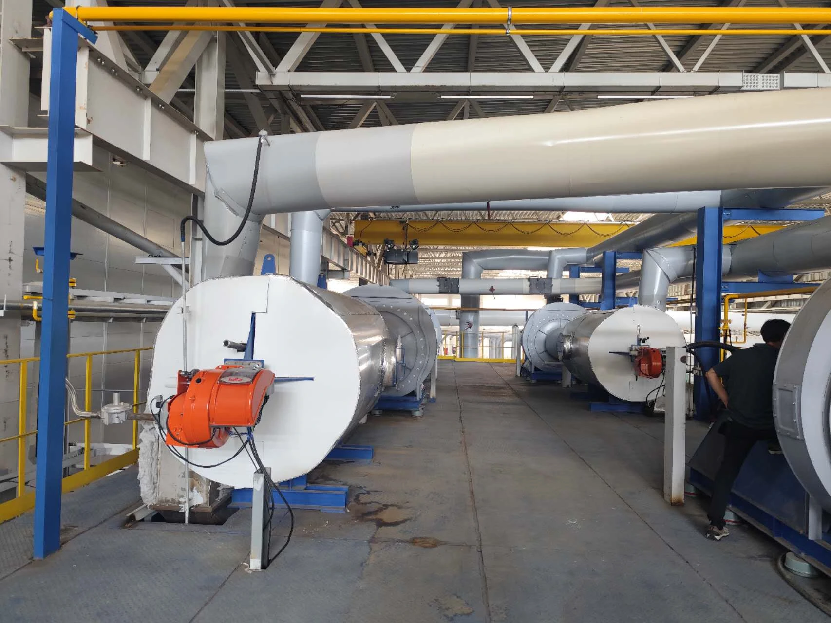
The application was a burner system for a rock wool manufacturing plant in Moscow, Russia. The installed configuration consisted of:
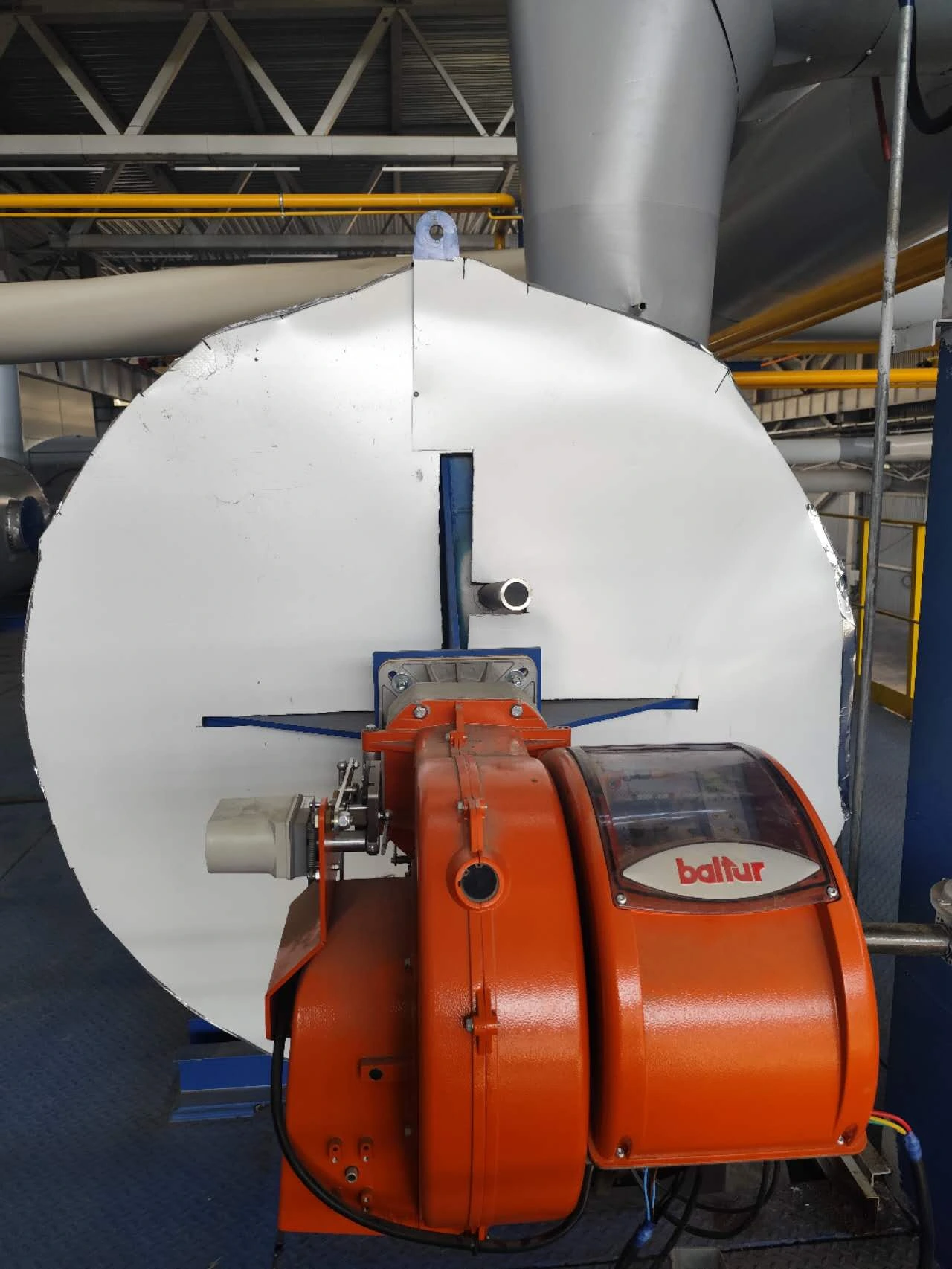
- Four Baltur TBG 80 LX P burners
- One Baltur TBG 200 LX P burner
Baltur’s model-specific sales sheets identify both TBG 80 LX P and TBG 200 LX P as two-stage gas burners. In this project, staged operation made correct ignition-position and high-fire-position adjustment central to the commissioning scope. Model selection and project suitability remain dependent on the required heat output, fuel and gas-train conditions, furnace interface, voltage, process temperature, control philosophy, and site environment.
Burner Specifications
According to Baltur’s April 2025 English sales sheets, both models are two-stage gas burners designed for staged heat delivery. The technical data below provides the output range, electrical requirements, motor rating, emissions class, and natural-gas reference condition for each model. See the official TBG 80 LX P data sheet [1] and TBG 200 LX P data sheet [2].
| Model / Quantity | Fuel and Operation | Rated Thermal Output | 50 Hz Electrical Data | Technical Reference |
|---|---|---|---|---|
| TBG 80 LX P / 4 units Part no. 18490010 |
Gas burner; two-stage operation. Published data use natural gas at Hi = 35.80 MJ/m³ (0°C, 1013 mbar) as the reference condition. | 120–800 kW EN 676 emissions class 3 |
3N AC, 50 Hz, 400 V 1.1 kW motor |
Baltur sales sheet [1] |
| TBG 200 LX P / 1 unit Part no. 18760010 |
Gas burner; two-stage operation. Published data use natural gas at Hi = 35.80 MJ/m³ (0°C, 1013 mbar) as the reference condition. | 200–1,900 kW EN 676 emissions class 3 |
3N AC, 50 Hz, 400 V 3.0 kW motor |
Baltur sales sheet [2] |
| Project Item | Verified Project Information |
|---|---|
| Location | Moscow, Russia |
| Application | Rock wool manufacturing plant burner system |
| Burner configuration | 4 × Baltur TBG 80 LX P; 1 × Baltur TBG 200 LX P |
| Commissioning scope | Wiring, start-up, staged-position adjustment, troubleshooting, training, remote control integration, and relay-circuit modification |
| Operating verification | Repeated start-stop tests, low-fire temperature-control observation, high-fire setpoint verification, and remote-signal function checks |
What On-Site Burner Installation and Commissioning Work Was Completed?
1. Field Wiring and Cable-Number Verification
Before start-up, the field wiring was checked against the assigned cable numbers. This step helped confirm that the installed connections corresponded to the intended burner and control functions. For a multi-burner installation, systematic line-number verification reduces the risk of testing the correct command against the wrong field circuit.
2. Start-Up Testing and Ignition-Position Adjustment
Each burner was started under controlled site conditions. The ignition position was adjusted to support repeatable light-off during subsequent start-stop trials. This was not treated as a single successful ignition event; the team used repeated operation to determine whether the setting remained stable.
3. High-Fire Position Setting
After the ignition stage was established, the high-fire position was set and checked against the plant’s required operating temperature. The purpose of this step was to confirm that the burner system could move from its lower operating stage to the required high-fire condition and raise the process to the specified temperature.
4. Investigation of Abnormal Operating Noise
Abnormal noise was identified during operation and addressed as part of the industrial burner troubleshooting scope. The issue was handled together with the staged burner adjustment rather than as an isolated acoustic symptom. This approach matters because operating noise can be influenced by the relationship among burner settings, airflow, mechanical installation, and actual furnace conditions.
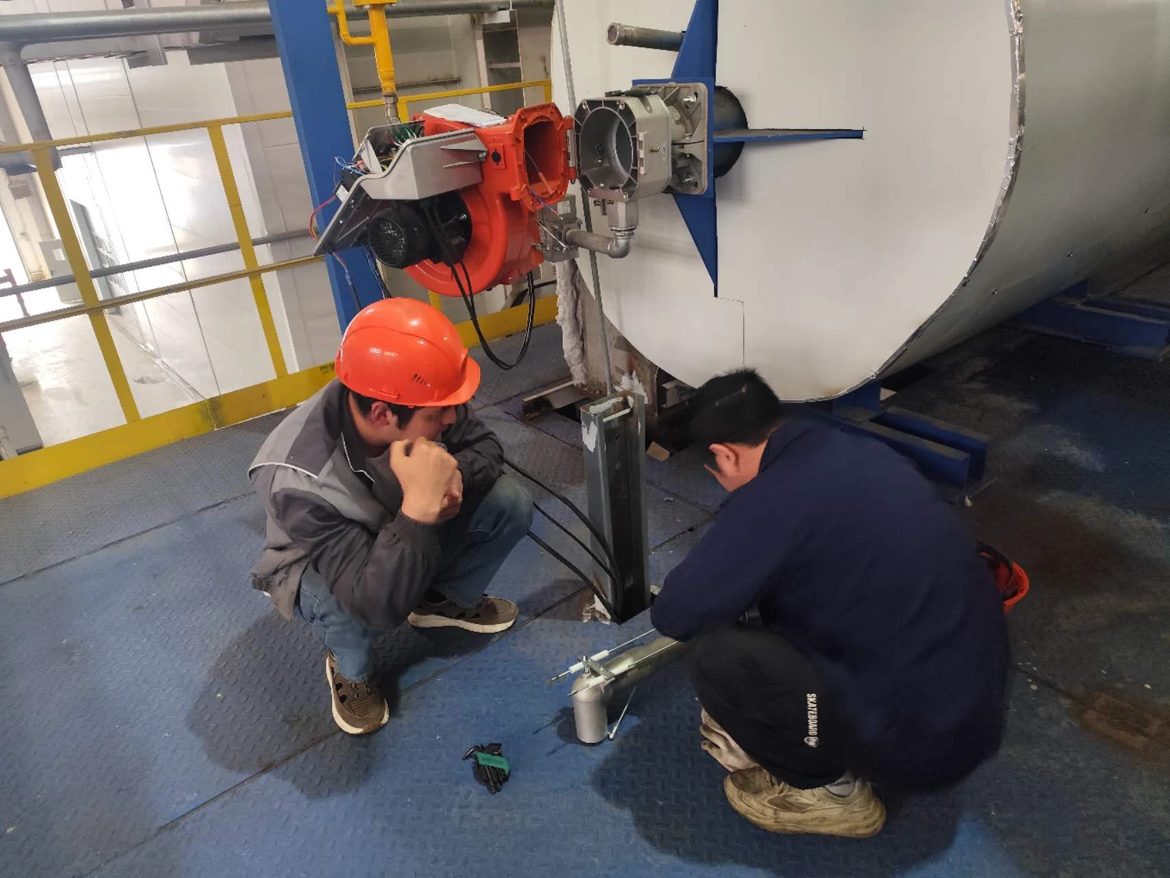
5. Ignition-Assembly Service Training
On-site operators and maintenance personnel were trained on the removal and reinstallation of the ignition assembly. The procedure was demonstrated beside the installed burner so the training reflected the available access space and the actual equipment arrangement. This gives maintenance teams a practical reference for future inspection and service work.
6. Remote Signal Integration and Relay-Circuit Modification
The burner control system integration work connected the burner package with the plant’s remote control functions. Start, stop, alarm reset, and temperature-setting signals were checked. The air-pressure-switch circuit was also modified by changing to a relay arrangement so the field logic could operate as required.
This part of commissioning demonstrates why controls cannot be treated as an accessory to the burner. The burner sequence, protective devices, plant commands, and temperature controller must exchange signals correctly before the system can be handed over for routine operation. Heatflam supports this type of burner-system integration and customized industrial combustion solution for site-specific process requirements.
What Problems Were Solved During Commissioning?
The commissioning team did more than confirm that power was available and the burners could start. The site work addressed four practical integration risks:
- Connection accuracy: field wiring and cable numbers were verified before functional testing.
- Unstable or unsuitable staged settings: ignition and high-fire positions were adjusted under real operating conditions.
- Abnormal operating noise: the symptom was investigated during burner adjustment and site operation.
- Control-interface mismatch: remote commands were integrated and the air-pressure-switch circuit was adapted with a relay.
These tasks were connected. A wiring issue can look like a burner fault; an incorrect staged position can affect temperature response; and a local burner that operates normally may still fail the plant’s remote-control sequence. Effective Baltur burner commissioning therefore requires checks at equipment, combustion, electrical, and plant-control levels.
How Was the Rock Wool Plant Burner System Tested?
The test plan was based on repeatability and functional response rather than a single start-up demonstration. The on-site verification included:
- Repeated start-stop testing to observe whether ignition remained stable over multiple cycles.
- Low-fire temperature-control observation to check stable control and confirm that the process did not exceed the target temperature.
- High-fire operating verification to determine whether the system could reach the required set temperature.
- Remote function checks for start, stop, alarm reset, and temperature-setting signals.
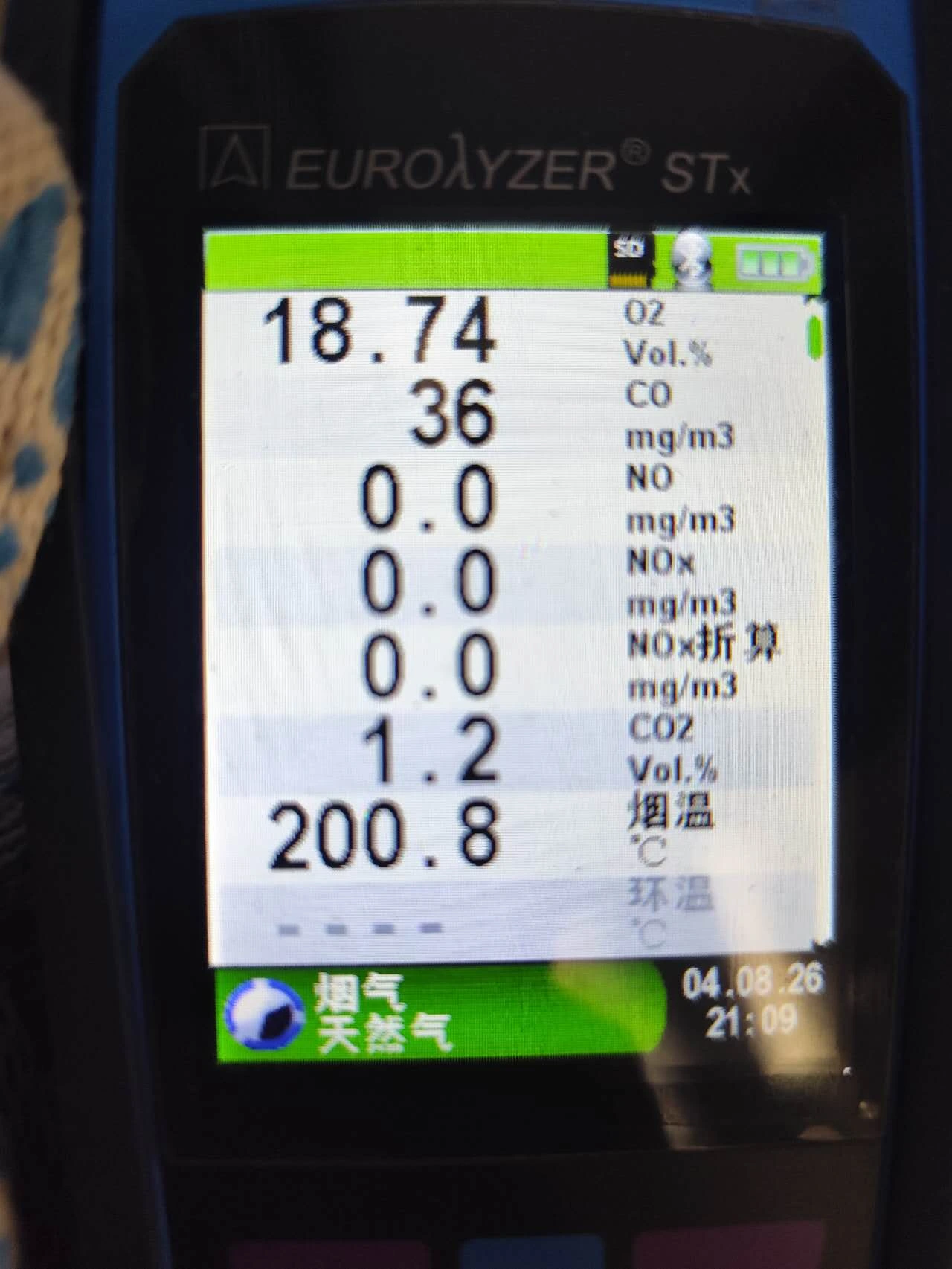
- On-site combustion testing with an analyzer display used to observe operating parameters under actual conditions.
Final Commissioning Results
The completed tests produced the following observed results for the installed system:
- Stable ignition after repeated start-stop tests.
- Stable low-fire temperature control without overshoot.
- High-fire operation reached the required set temperature.
- Remote start, stop, alarm-reset, and temperature-setting signals operated normally.
Together, these results confirmed that the burner package, staged settings, temperature-control response, and remote interface were functioning as required at the time of on-site testing. Operator training also formed part of the handover, helping the site team understand the ignition-assembly service procedure.
What This Project Shows About Industrial Burner Commissioning
A reliable commissioning process follows the signal path from the plant control system to the burner and then confirms the resulting process response. For this Moscow rock wool project, the work combined physical installation checks, burner adjustment, troubleshooting, operator training, relay logic, and functional testing.
For future projects, buyers should define the fuel, required heat output, process temperature, furnace or hot-air-system interface, available gas pressure, electrical supply, control signals, applicable local requirements, installation space, and test acceptance criteria before equipment selection. These inputs help the burner supplier and site team plan the correct hardware, control architecture, and commissioning sequence.
A Practical Commissioning Checklist for Similar Burner Systems
The following sequence can help a plant team organize a similar commissioning job. It is general engineering guidance, not a substitute for the burner manufacturer’s instructions, the approved electrical drawings, or site-specific safety procedures.
- Confirm the design basis: burner model, fuel, required output, furnace interface, supply pressure, voltage, control philosophy, and acceptance criteria.
- Complete cold checks: verify wiring numbers, terminals, grounding, rotation where applicable, valves, pressure switches, ignition components, and mechanical installation before introducing fuel.
- Verify permissives and interlocks: confirm that the burner can start only when the required plant and burner conditions are satisfied.
- Establish ignition: observe the complete start sequence and adjust the ignition position using the approved procedure and instruments.
- Check low-fire control: observe temperature response, flame stability, and whether the process approaches the setpoint without unacceptable overshoot.
- Set and verify high fire: confirm the staged transition and verify that the process can reach the required operating condition without abnormal noise or unstable operation.
- Test plant controls: check remote start, stop, reset, setpoint, status, and alarm functions one by one against the I/O list.
- Prove repeatability: run repeated start-stop cycles and record the result instead of accepting one successful start.
- Document and hand over: record final settings, unresolved limitations, test conditions, alarm behavior, and operator-maintenance procedures.
If a Burner Shows Similar Symptoms, What Should Be Checked?
A symptom does not identify one universal cause. The table below gives practical starting points for a qualified commissioning team. Testing must follow the approved manual, drawings, lockout procedures, and site safety rules.
| Observed Symptom | Useful Checks | Evidence to Record |
|---|---|---|
| Ignition is inconsistent | Start-sequence status, ignition-assembly condition and position, flame-detection signal, fuel and air conditions, and interlock state | Cycle count, failure point, alarm code, operating conditions, and corrective action |
| Abnormal noise appears during operation | Operating stage, burner and duct mounting, fan or airflow condition, combustion-head setting, fuel-supply condition, and furnace response | When the noise begins, load stage, relevant settings, and whether the symptom changes after adjustment |
| Temperature overshoots at low fire | Low-fire setting, temperature-sensor location and signal, controller parameters, process delay, and burner staging logic | Setpoint, temperature trend, stage command, sensor reading, and time response |
| Remote command does not operate correctly | I/O mapping, voltage and common reference, relay logic, command duration, permissive state, alarm-reset conditions, and local/remote selection | Command at the plant controller, signal at the burner terminal, resulting burner status, and any active interlock |
Frequently Asked Questions
Send Heatflam your fuel type, heat output, process temperature, gas pressure, electrical supply, application details, installation drawings, control requirements, site conditions, and test criteria. Our engineers can review the burner selection, integration scope, and commissioning plan.
REFERENCES AND DATA SOURCES:
- Baltur S.p.A. — TBG 80 LX P / TBG 85 P official English sales sheet, edition 2025-04 (accessed 2026-08-05).
- Baltur S.p.A. — TBG 200 LX P / TBG 210 P official English sales sheet, edition 2025-04 (accessed 2026-08-05).
- Baltur S.p.A. — TBG LX P official series page (accessed 2026-08-05).
- Baltur S.p.A. — official product documentation portal (accessed 2026-08-05).
