
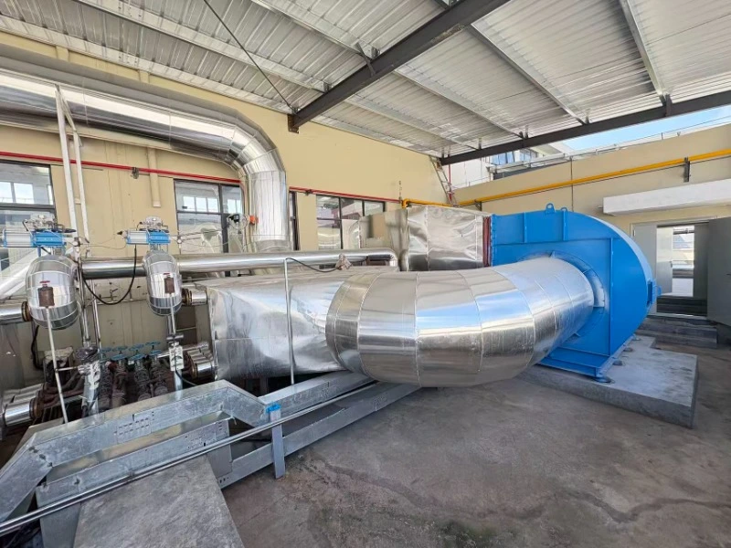
Calibrating the Air-Fuel Ratio (AFR) and Oxygen Trim
Resetting the digital air-fuel ratio prevents the baseline 4.5% stack heat loss associated with an uncalibrated industrial burner system [3]. Maintaining excess oxygen strictly between 1.5% and 2.0% across the firing curve ensures fuel energy transfers to the process rather than heating parasitic atmospheric nitrogen.
During an annual maintenance cycle, technicians must extract and validate the zirconium dioxide (ZrO2) cells within the O2 trim system. When an O2 sensor becomes fouled with unburned carbon or silica dust, its internal reference voltage drifts, often causing the controller to inject up to 15% excess combustion air to compensate for the false low-oxygen reading. According to thermodynamic principles, for every 22°C increase in stack exhaust temperature driven by excess air volume, the system suffers a direct 1% loss in boiler or oven thermal efficiency.
Mechanically linked industrial burner systems utilizing cam-and-shaft arrangements suffer from mechanical hysteresis, where vibration and thermal expansion degrade linkage precision by ±2% over a 12-month operational window. Upgrading to or recalibrating independent servomotor setups via digital positioning guarantees a repeat accuracy of 0.1 angular degrees on the fuel and air valves. Technicians must conduct a multi-point exhaust gas analysis using a calibrated combustion analyzer, manually verifying CO levels remain below 10 ppm while locking the O2 trim target at 1.5% during maximum continuous rating (MCR).
Inspecting Flue Gas Recirculation (FGR) Dampers for NOx Control
Clearing carbon deposits from the FGR damper guarantees the system maintains the 15–20% volumetric exhaust recirculation required to suppress thermal NOx formation [4]. If FGR mass flow drops by just 5% due to mechanical binding, localized flame temperatures exceed 1,400°C, instantly spiking NOx emissions above the 30 mg/Nm³ regulatory threshold [2].
Routine inspection of the FGR circuit requires verifying the static pressure differential across the recirculation fan. The industrial burner system relies on a precise mass flow of cooler, oxygen-depleted exhaust gas to dilute the primary air stream, lowering the adiabatic flame temperature. Technicians must inspect the VFD (Variable Frequency Drive) parameters controlling the FGR fan, ensuring the feedback loop scan rate remains under 50 milliseconds. A sluggish FGR response during a rapid load change induces an oxygen-starved state, forcing CO emissions to spike past 100 ppm within 3 seconds.
Furthermore, the stainless steel damper blades within the high-temperature FGR ducting are susceptible to thermal warping. Using a micrometer, technicians must confirm the blade clearances do not exceed 2.0 mm when the actuator commands a 0% closed position. Leakage through the FGR duct during the pre-purge sequence delays burner light-off and extends the purge cycle by 30 to 45 seconds, wasting 0.5% of total system energy per event.
Tuning the PID Control Loop for Thermal Stability
Recalibrating the proportional-integral-derivative (PID) controllers restores firing rate accuracy, maintaining target process temperatures within a tight ±0.5°C margin [5]. Eliminating control loop oscillation restores the industrial burner system’s 10:1 turndown capability, saving 0.5% in latent energy per avoided safety purge cycle [6].
Maintenance engineers must connect a diagnostic terminal to the burner management system (BMS) to analyze the historical trend graphs of the PID loop. If the proportional band (P) is set too narrow, the gas valve servomotor will “hunt,” oscillating the firing rate by ±5% continuously. This rapid modulation accelerates the mechanical fatigue of the servo gearing, reducing the expected lifespan of the actuator from 50,000 hours to 15,000 hours. Technicians must perform a step-response test, commanding a 20% instantaneous load increase and adjusting the integral (I) and derivative (D) parameters to achieve process equilibrium within 45 seconds without exceeding a 1.0°C overshoot.
Digital industrial burner systems often integrate cross-limiting control architecture. Maintenance routines must verify the software parameters ensuring the air damper leads the gas valve by 250 milliseconds during a firing rate increase, and lags the gas valve by the identical duration during a decrease. This specific timing configuration prevents transient fuel-rich conditions, strictly eliminating soot deposition inside the heat exchanger tubes.
Cleaning the Combustion Head and Gas Nozzle Geometry
Removing soot and particulate buildup from the combustion head maintains the designated 30–40 m/s fuel injection velocity [7]. Correcting fuel dispersion geometry prevents flame impingement on the refractory lining, preventing a 25% reduction in the mean time between failures (MTBF) of the burner quarl.
The combustion head operates in the most extreme environment within the industrial burner system, enduring constant radiant heat and chemical oxidation. During downtime, operators must remove the gas spuds and inspect the orifices using a go/no-go pin gauge. An increase in orifice diameter by just 0.5 mm due to abrasive wear alters the fuel pressure required to reach MCR, directly lowering the gas injection velocity. Slower fuel velocity retards the mixing rate of natural gas and primary air, creating a long, lazy flame that loses its aerodynamic stability.
For premix industrial burner systems, the sintered metal or ceramic mesh covering the burner head must be subjected to an ultrasonic cleaning bath. Any blockage exceeding 10% of the total surface area forces the system static pressure to rise above 15 mbar, pushing the combustion blower outside of its optimal fan curve. Reassembling the combustion head requires torqueing all bolts to exactly 45 Nm using anti-seize compound rated for 1,200°C to prevent cold-welding of the threads.
Validating Flame Scanners and Electrical Interlocks
Testing the ultraviolet (UV) or infrared (IR) flame scanners guarantees an actuation response time of strictly under 3.0 seconds during a total flameout event [8]. Maintaining a Flame Signal Intensity (FSI) above 3.0 VDC eliminates 90% of unscheduled nuisance lockouts caused by blinded sensory equipment.
Flame scanners are the primary safety mechanism of any industrial burner system. Over a 12-month operating period, the quartz lens of a UV scanner accumulates microscopic layers of unburned hydrocarbons and ambient plant dust, refracting the UV radiation away from the phototube. Maintenance protocol demands cleaning the lens with a non-abrasive isopropyl alcohol solution. Afterward, technicians must measure the microampere (µA) or VDC output at the BMS terminal block during the low-fire state. If a UV tube registers below 2.5 VDC on a 5.0 VDC scale, the vacuum tube itself is degraded and requires immediate replacement to prevent a false-loss-of-flame shutdown.
Concurrently, all electrical safety interlocks require physical validation. Technicians must bleed down the main gas line to test the Low Gas Pressure (LGP) switch, verifying it drops the safety relay circuit exactly at 20 mbar (or the OEM specified threshold). The High Gas Pressure (HGP) and Low Combustion Air (LCA) switches must be subjected to identical physical stimulation. Utilizing a digital multimeter, technicians must verify the resistance across the closed relay contacts remains below 0.2 ohms, ensuring no voltage drops compromise the 120 VAC safety chain.
Refractory Inspection and Thermal Imaging Diagnostics
Utilizing infrared thermography to detect refractory degradation limits casing heat loss to an absolute maximum of 1.5% of total system thermal input [9]. Identifying and patching micro-fissures in the burner throat stabilizes the aerodynamic pressure drop across the combustion head at a constant 15 mbar.
The refractory throat (quarl) shapes the root of the flame and stabilizes the combustion front through radiant heat reflection. During the cooling phase of an industrial burner system, differential thermal contraction induces hairline cracks. During maintenance, technicians must perform a tactile and visual inspection, measuring crack width using a feeler gauge. Any fissure exceeding 3.0 mm in width must be routed out and packed with a high-alumina (>85% Al2O3) castable refractory rated for 1,600°C.
Failure to repair these geometric deformities alters the vortex dynamics of the incoming combustion air. If a chunk of refractory falls into the air stream, it causes asymmetric flame rotation, concentrating 60% of the thermal load onto one side of the furnace or boiler wall. Utilizing an external thermal camera during operation allows technicians to scan the steel outer casing of the industrial burner system. Any localized hot spot registering above 60°C over ambient temperature confirms a breach in the internal insulation layer, demanding an immediate offline teardown to prevent structural steel warping.
Frequently Asked Questions (FAQ)
REFERENCES AND DATA SOURCES:
- [1] ASME PTC 4-2013, Performance Test Codes for Fired Steam Generators.
- [2] European Emission Control Directive 2023/12/EU (NOx Compliance Limits).
- [3] US Department of Energy, “Industrial Energy Efficiency and Stack Loss Parameters,” 2024.
- [4] Handbook of Combustion and Flame Dynamics, “Flue Gas Recirculation Strategies,” Section 8.
- [5] Journal of Thermal Process Control, “PID Loop Accuracy in Industrial Steam Generation,” Vol 12.
- [6] North American Combustion Handbook, 3rd Edition, “Cycle Loss Analysis in Fired Equipment.”
- [7] International Journal of Combustion Aerodynamics, “Fuel Injection Velocity and Flame Impingement,” 2025.
- [8] NFPA 85: Boiler and Combustion Systems Hazards Code, 2024 Edition.
- [9] ASTM C71: Standard Terminology Relating to Refractories.