What Was Required for This Waste-Gas Treatment Project?
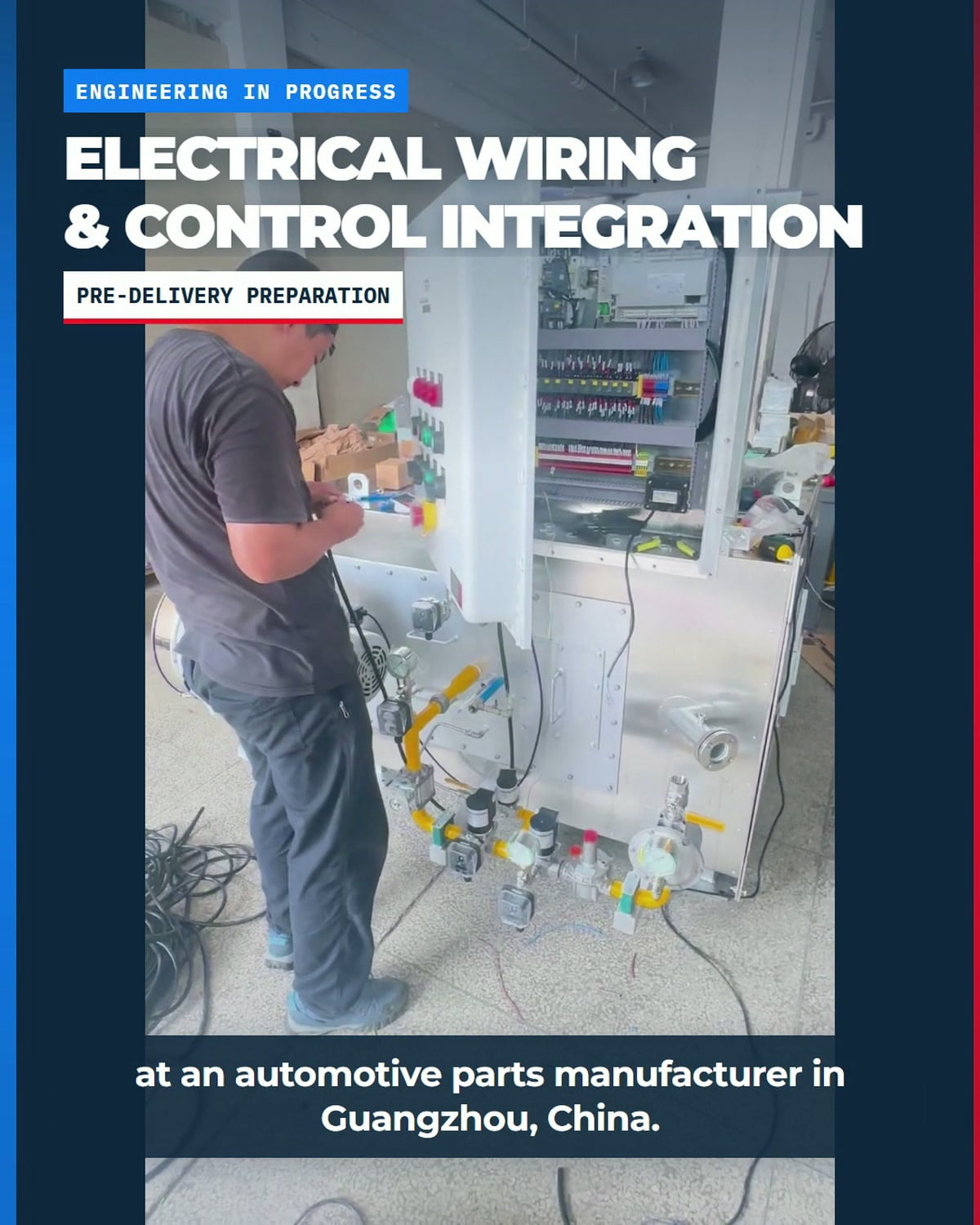
The project required a custom industrial combustion system for a catalytic waste gas treatment application. The specified heat load was 300,000 kcal/h. The customer is an automotive parts manufacturer in Guangzhou, China.
A waste gas treatment burner is only one part of the working package. The project also required the burner, gas train system, combustion controls, safety components, electrical cabinet, field connections, and related equipment to be integrated around the actual process requirements.
| Project item | Confirmed project information |
|---|---|
| Application | Catalytic waste-gas treatment |
| Heat load | 300,000 kcal/h |
| Customer profile | Automotive parts manufacturer |
| Project location | Guangzhou, China |
| Documented stage | Manufacturing, assembly, electrical wiring, and pre-delivery preparation |
| Next service stage | On-site commissioning, combustion tuning, and operational checks after installation |
Why Does Catalytic Waste-Gas Treatment Need Application-Specific Engineering?
The U.S. Environmental Protection Agency describes a catalytic incinerator, also called a catalytic oxidizer or catalytic reactor, as a destruction-by-oxidation technology. Its technical guidance also identifies the inlet gas stream, operating conditions, catalyst selection, and contaminants as important design considerations. [1]
Peer-reviewed reviews reach the same engineering conclusion: catalytic performance depends on the pollutant source, reaction conditions, catalyst formulation, and potential deactivation mechanisms. [2] [3] This is why an industrial combustion system for waste gas treatment should be selected from process data, not from heat load alone.
- Confirm the waste-gas composition and any substances that affect the catalyst or upstream equipment.
- Define the gas flow range, inlet temperature, required process temperature, and expected load changes.
- Match the burner, gas train, controls, safety sequence, installation layout, and commissioning plan to the same operating basis.
What Is Included in the 300,000 kcal/h Combustion System?
The project is engineered as a complete package rather than a stand-alone industrial burner system. The documented scope brings the main combustion and control elements together before delivery:
- Burner: the combustion device selected for the required project heat load and process duty.
- Gas train system: the assembled valves, pressure-indicating and regulating components, piping, and associated safety hardware shown in the project.
- Combustion control system: the control cabinet, electrical components, terminals, cables, and integrated control connections.
- Equipment integration: the supporting structure and related assemblies needed to prepare the complete system for installation.
This integrated approach gives the engineering team a common basis for component layout, electrical wiring, control logic, installation interfaces, and the later combustion system commissioning stage.
How Are Electrical Wiring and Control Integration Completed?
The project video shows the engineer working inside the control cabinet, connecting terminals and cables, and checking the electrical components. This is the pre-delivery integration stage, where the individual devices are organized into one combustion control system.
Control integration must reflect the actual system sequence and site interfaces. The required design inputs include the burner operating sequence, permissives and interlocks, valve-train devices, flame-safeguard functions, process signals, power supply, field wiring scope, and shutdown requirements. The exact logic and electrical specification are project-specific and are not published in this case.
Why Integrate the Burner, Gas Train, Controls, and Safety Components?
A custom combustion system for waste gas treatment has multiple interfaces. Fuel delivery, burner operation, electrical controls, process demand, safety devices, and the treatment equipment must work from a coordinated design basis. The EPA Control Cost Manual treats oxidizer selection and design as a system-level engineering task that depends on the process stream and equipment configuration. [4]
For this HEATFLAM project, the integration work is visible in the relationship between the burner, gas train, control cabinet, wiring, safety components, and equipment structure. The objective at this stage is to prepare a coordinated system for delivery and installation—not to publish operating-performance claims before commissioning.
What Happens During On-Site Burner Commissioning?
The project does not end when the equipment leaves the workshop. After installation, a HEATFLAM engineer is scheduled to visit the customer site for on-site burner commissioning, combustion tuning, and operational checks.
The commissioning scope is completed against the approved project documentation and actual site conditions. Typical project checks must be defined for the installed configuration and can include installation interfaces, electrical signals, valve-train status, permissives and shutdowns, ignition sequence, flame supervision, combustion adjustment, load response, and operating observations. Acceptance criteria remain project-specific.
What Information Is Needed for a Similar Custom Combustion System?
A useful request for quotation should define the process and site conditions before equipment selection. Send the following information to the engineering team:
- Application and process description, including the role of the combustion system in the treatment process.
- Required heat output and operating-load range.
- Fuel type, available inlet pressure, and fuel-property information.
- Waste-gas composition, concentration range, flow, inlet temperature, and contaminants relevant to the treatment equipment.
- Target process temperature, control range, and required operating sequence.
- Power supply, control interface, installation space, site conditions, applicable code, and commissioning scope.
Frequently Asked Questions
Send your process data, fuel conditions, heat-load range, control requirements, site information, and commissioning scope for an engineering review.
REFERENCES AND DATA SOURCES:
- U.S. Environmental Protection Agency — Air Pollution Control Technology Fact Sheet: Catalytic Incinerator (EPA-452/F-03-018, published 2003-07).
- Chemical Reviews — Recent Advances in the Catalytic Oxidation of Volatile Organic Compounds: A Review Based on Pollutant Sorts and Sources (published online 2019-02-27).
- Royal Society of Chemistry, Catalysis Science & Technology — Recent Progress on Catalysts for Catalytic Oxidation of Volatile Organic Compounds: A Review (first published 2022-09-29).
- U.S. Environmental Protection Agency — Chapter 2: Incinerators and Oxidizers (document released 2017-11; page updated 2026-07-21).
