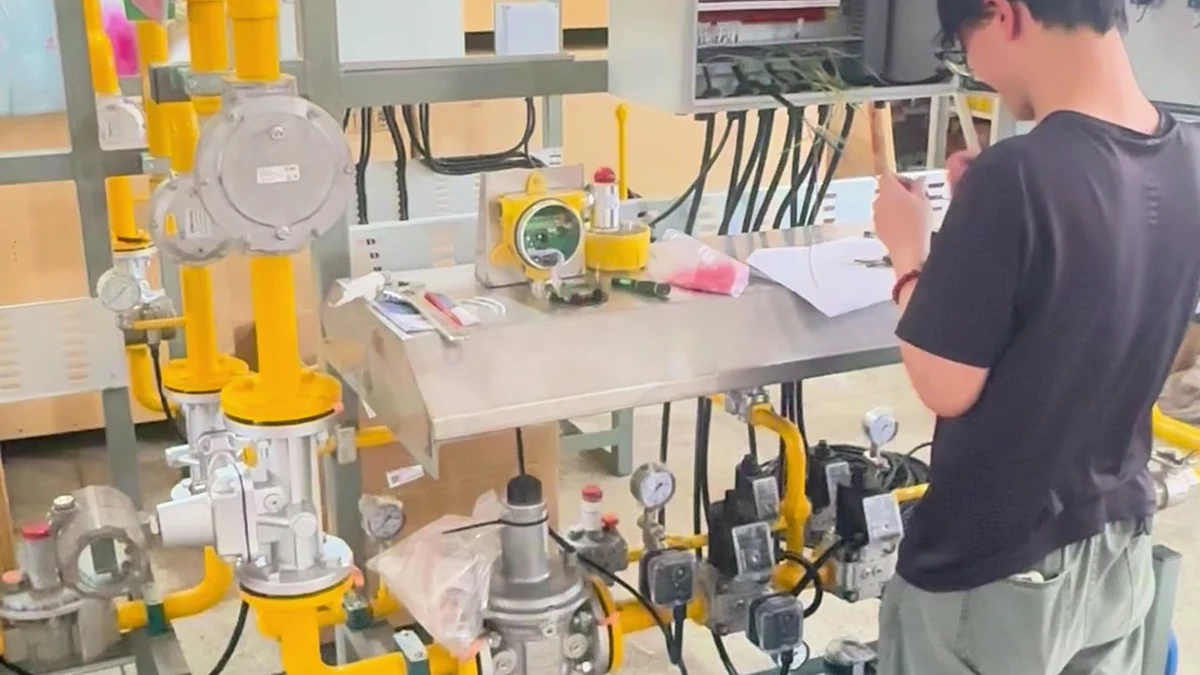
This industrial combustion system for automotive paint line applications was engineered around a rated heat output of 750 kW and prepared for an automotive project in Thailand. The work shown is not a staged product demonstration: it records final wiring and inspection in a real engineering environment, with the control cabinet open and the valve train, pipework, instruments, and associated combustion equipment visible.
The project illustrates how Heatflam approaches customized industrial combustion systems: define the process duty, integrate the burner and fuel-handling components, connect the control functions, and inspect the assembled system before it moves to the next project stage.
Project Snapshot: 750 kW System for Thailand
| Project item | Confirmed scope |
|---|---|
| Application | Automotive paint-line project |
| Destination | Thailand |
| Rated capacity | 750 kW |
| Integrated equipment | Burner, gas valve train, combustion controls, control cabinet, piping, instruments, and associated equipment |
| Process applications | Clear Coat / Moisture Process |
| Stage shown | Final wiring and inspection of one system |
Watch the Project Video
The vertical project video documents the engineer, open control cabinet, valve train, gauges, actuators, pipework, and overall equipment layout during final wiring and inspection.
What Does This Automotive Paint Line Combustion System Include?
An automotive paint line burner system is more than a burner selected from a catalogue. The burner has to operate as part of an industrial process heating system that also manages fuel delivery, combustion air, ignition, flame supervision, operating commands, alarms, and the interface with the process equipment.
The project shown integrates the following visible engineering elements:
- Burner and associated equipment: the heat-generation section of the system.
- Industrial gas valve train: the assembled fuel-handling path with valves, regulating components, pressure instruments, and connected pipework.
- Combustion control system: the control cabinet, wiring, operating logic, and interfaces used to coordinate the combustion sequence with the process.
- Instruments and actuators: devices that provide operating feedback and execute control commands.
- Mechanical integration: the frame, piping routes, equipment spacing, and service access that turn individual components into a practical assembly.
This system-level view is consistent with the U.S. Department of Energy’s process-heating guidance, which recommends evaluating heat generation, heat transfer, containment, controls, and component interactions as one system rather than as isolated devices [2].
Why Process Matching Matters in Automotive Paint-Line Heating
Automotive coating lines contain several distinct coating and thermal-process stages. U.S. EPA guidance identifies topcoat operations as including basecoat and clearcoat, alongside other primary automotive coating stages [1]. The project described here covers Clear Coat and Moisture Process applications; those labels define two process configurations without implying that two units appear in the video.
Published automotive paint-oven research also shows why the heating duty cannot be reduced to a single nameplate number. Drying and curing behaviour depends on the required temperature profile, residence time, air movement, heat transfer to different body sections, and the operating zones of the oven [4] [5].
For that reason, a customized industrial combustion system must be matched to the real process: fuel conditions, heat demand, control range, process temperature, airflow, equipment geometry, operating sequence, and plant interface. The 750 kW rating defines the project’s heat-output scale; it does not replace the engineering data needed to select or reproduce the system.
How Do the Gas Valve Train and Combustion Controls Work Together?
The gas valve train supplies and regulates fuel within the engineered operating envelope. The combustion controls coordinate start permission, ignition, flame supervision, operating demand, shutdown, and alarm handling. Their exact arrangement must follow the selected burner, fuel pressure, control philosophy, process equipment, and applicable site requirements.
ISO 13577-2:2023 identifies fuel pipework, combustion-air supply, burners, ignition devices, and safety-related control functions as connected parts of combustion and fuel-handling systems for industrial thermoprocessing equipment [3]. This does not establish project-specific compliance. It shows why valve-train hardware, burner equipment, ignition, and controls have to be reviewed as an integrated safety and operating system.
What Is Checked During Final Wiring and Inspection?
The video focuses on the stage where engineering details become a complete control and mechanical assembly. The engineer works at the open control cabinet while the connected valve train and instrumentation remain visible. This makes the relationship between the electrical and mechanical parts of the system clear.
A project-specific inspection plan is defined by the approved design and site requirements. Relevant checks can include terminal identification, wiring continuity, component labels, instrument ranges, valve orientation, piping connections, cabinet layout, protective devices, input/output mapping, alarm logic, and the documented sequence of operation. Functional combustion testing and commissioning requirements must be confirmed separately for the actual installation.
What Information Is Required for a Similar Project?
To engineer an industrial burner system for the automotive industry, submit the process data that defines heat demand and integration. A useful RFQ should include:
- Fuel type, available inlet pressure, and fuel composition where relevant.
- Required heat output and whether it is nominal, maximum, or calculated process duty.
- Target process temperature, temperature profile, load, residence time, and operating schedule.
- Heating method, oven or duct arrangement, airflow, pressure conditions, and available installation space.
- Required turndown, control philosophy, PLC or DCS interface, voltage, and signal list.
- Site country, installation environment, hazardous-area classification where applicable, and the codes or standards specified by the project.
- Existing drawings, equipment layout, interface dimensions, and the expected engineering and documentation scope.
Frequently Asked Questions
Send your fuel conditions, heat output, process temperature profile, site layout, and control requirements. HEATFLAM will review the application and define the appropriate engineering scope.
REFERENCES AND DATA SOURCES:
- U.S. Environmental Protection Agency — Control Techniques Guidelines for Automobile and Light-Duty Truck Assembly Coatings (Published 2008-09).
- U.S. Department of Energy — Improving Process Heating System Performance: A Sourcebook for Industry, Third Edition (Published 2015).
- International Organization for Standardization — ISO 13577-2:2023, Industrial furnaces and associated processing equipment — Safety — Part 2: Combustion and fuel handling systems (Published 2023-12-15).
- Progress in Organic Coatings — Automotive painting process: Minimizing energy consumption by using adjusted convective heat transfer coefficients (Published 2020-03).
- Applied Thermal Engineering — A heat exchanger analogy of automotive paint ovens (Published 2013-11-03).
