Project Overview: A Custom Combustion System for Waste Incineration
A waste-incineration project cannot be defined by burner capacity alone. The combustion equipment must also be arranged around the combustion chamber, available installation space, fuel-gas conditions, control philosophy, piping interfaces, and the operating requirements of the wider process.
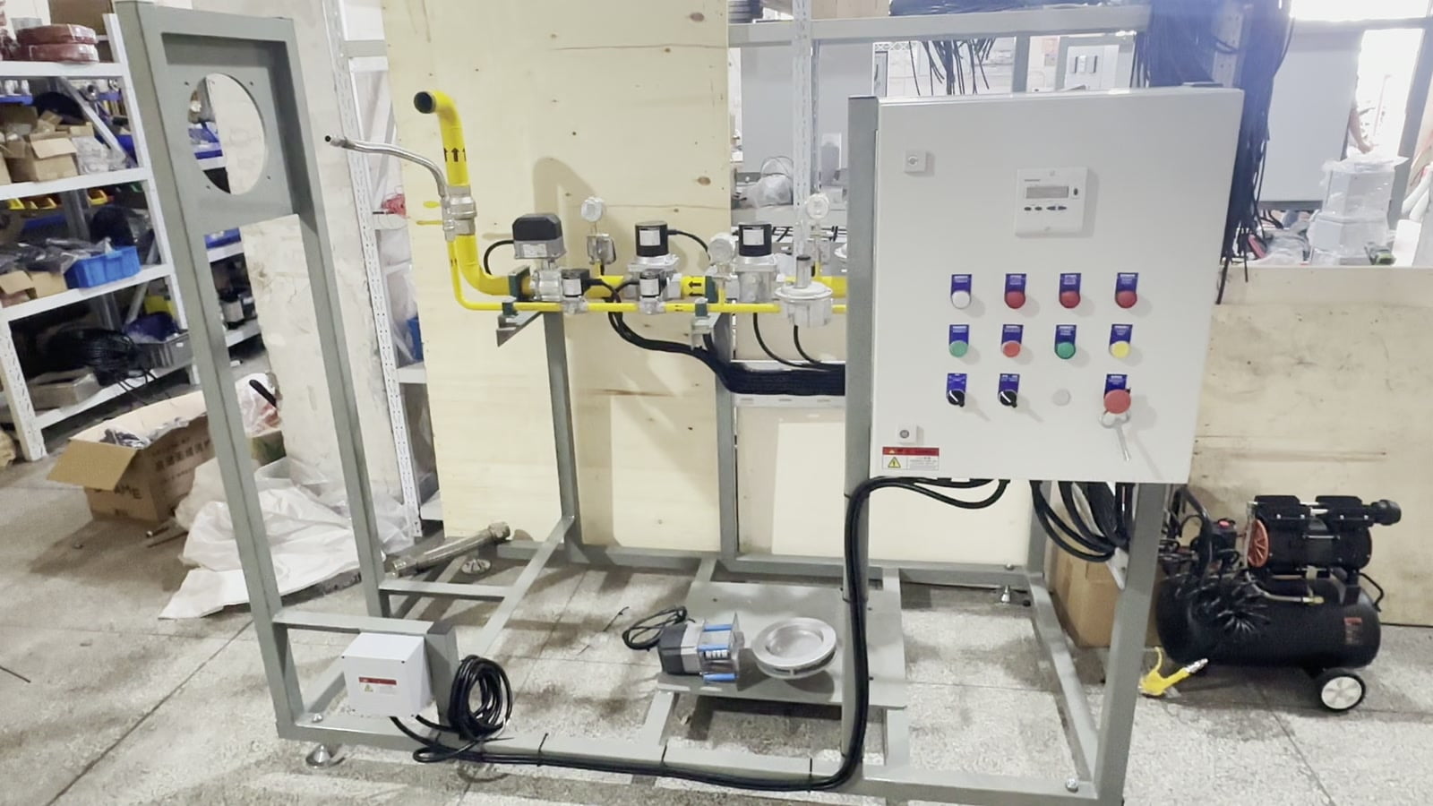
This HEATFLAM project has a stated project capacity of 1,250,000 kcal/h. Its configuration is an extended integrated skid-mounted combustion system developed for a waste-incineration application. Rather than presenting separate components in isolation, the case shows how the burner, valve train, pressure-control hardware, piping, skid structure, and control cabinet are coordinated as one engineered package.
What Does the Project Configuration Include?
The video documents the visible configuration of this project package. It should be read as a case-specific arrangement, not as a universal specification for every waste incineration combustion system.
| Project item | Documented configuration | Engineering relevance |
|---|---|---|
| Heat output | 1,250,000 kcal/h | A project specification used together with chamber and process data. |
| Application | Waste incineration | The burner package must be coordinated with the actual thermal process. |
| Mechanical arrangement | Extended integrated skid | Provides a defined frame for the coordinated component layout. |
| Fuel-side equipment | Integrated gas valve train, pressure-control components, gauges, valves, and piping | Final selection depends on the confirmed fuel and supply conditions. |
| Controls | Integrated combustion control cabinet | Coordinates the combustion package according to the approved control logic and interfaces. |
| Burner section | Industrial burner assembly with an extended section | The interface must match the combustion chamber and project layout. |
Why Use an Extended Skid-Mounted Combustion System?
In this project, the skid provides a common mechanical base for the burner-related equipment, gas valve train, piping, and control cabinet. The extended format gives the engineering team space to organize the visible components and their connections within one project-specific assembly.
A skid-mounted combustion system can simplify package definition before shipment because component positions and interfaces are established around an approved layout. However, “skid-mounted” does not mean installation-independent. Site pipework, utility connections, ventilation, electrical supply, supports, access clearances, commissioning requirements, and applicable codes still need project review.
How Are the Gas Valve Train and Pressure-Control Components Integrated?
The real project footage shows the gas valve train and related yellow piping mounted along the skid. Regulators, pressure gauges, valves, and connecting pipework are arranged as part of the complete package. This makes the fuel-side assembly visible and accessible within the defined skid layout.
The exact gas valve train specification must be selected from confirmed operating data. Relevant inputs include gas type and composition, available inlet pressure, required burner pressure and flow, permitted pressure drop, control method, electrical supply, site environment, applicable code, and the required interface with the plant control system.
How Does Combustion Control Integration Support the Package?
The control cabinet is integrated with the combustion package so that burner operation and the associated field components can be coordinated through the project control architecture. The required sequence, permissives, alarms, shutdown logic, feedback signals, and plant communication must be defined for the actual application.
For wider process context, the European Commission’s Waste Incineration BAT conclusions identify continuous monitoring of parameters such as flue-gas flow, oxygen content, temperature, pressure, and water-vapour content, together with combustion-chamber temperature. These BAT conclusions are a regulatory reference for installations within their scope; they are not a project-specific compliance statement for the HEATFLAM package shown here.
How Is the Industrial Burner Assembly Matched to the Application?
The burner body and extended burner section shown in the video were arranged for this project’s combustion-chamber interface and process requirements. For a new waste incineration burner system, the burner cannot be selected from heat output alone. The engineering review should consider the chamber geometry, mounting arrangement, required firing range, fuel conditions, combustion-air arrangement, process temperature, backpressure, control method, and operating sequence.
This is where system integration matters. A burner, valve train, control system, and skid are separate hardware groups, but their interfaces determine whether the package can be installed and commissioned as an engineered combustion system. HEATFLAM develops customized industrial combustion solutions around the confirmed project conditions rather than treating every application as the same standard assembly.
From Engineering Drawing to Complete Combustion Package
Near the end of the video, the project moves from the completed equipment to the approved engineering drawing. The drawing communicates the intended assembly layout, component positions, skid arrangement, and equipment interfaces. The finished package then provides the physical result of that design and integration process.
The European Commission’s Waste Incineration BREF describes waste incineration as a wider process that can include waste handling, thermal treatment, energy recovery, flue-gas cleaning, wastewater treatment, and residue treatment. The equipment shown in this case is therefore correctly described as a combustion system package for a waste-incineration project, not as the entire incineration plant.
What Information Is Needed for a Similar Custom Project?
To evaluate a comparable industrial combustion system, the combustion engineering team needs more than a target capacity. A useful RFQ package should include:
- Application and process: incinerator type, chamber function, operating sequence, and intended duty.
- Heat requirement: required heat output, normal load, minimum load, and operating profile.
- Fuel data: gas type or composition, available pressure, temperature, and expected variation.
- Combustion chamber: drawings, dimensions, burner opening, refractory arrangement, backpressure, and access limitations.
- Utilities and electrical data: power supply, available combustion air, instrument air if applicable, and local interface requirements.
- Controls and communication: plant PLC/DCS interface, required signals, sequence philosophy, and remote communication protocol.
- Site requirements: installation space, ambient conditions, hazardous-area classification if applicable, and governing local codes.
Frequently Asked Questions
Send HEATFLAM your required heat output, fuel conditions, combustion-chamber drawing, process duty, site constraints, and control requirements for an engineering review.
REFERENCES AND DATA SOURCES:
- European Commission Joint Research Centre — Best Available Techniques (BAT) Reference Document for Waste Incineration (Published 2019; released on the EU Publications website 2020-01-07).
- European Commission — Implementing Decision (EU) 2019/2010 establishing BAT conclusions for waste incineration (Adopted 2019-11-12).
