
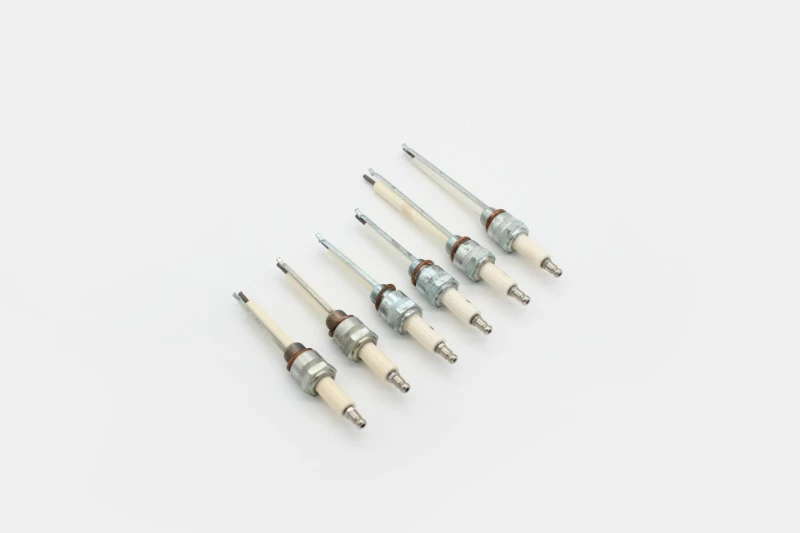
Ignition Electrodes and Ionization Probes: Common Burner Failure Points
Root-Cause Diagnosis
An ignition electrode fails when spark energy or position cannot light the fuel-air stream; an ionization probe fails when the controller cannot receive its specified rectified flame current. Published examples range from 0.7 μA to 6 μA, so compare readings with the exact controller manual before replacing either part [1][3][4].
An industrial gas burner can produce a visible spark yet fail to light, or establish a stable flame yet shut down as if no flame exists. These symptoms often involve the ignition electrode, flame monitoring electrode, ceramic insulators, cables, brackets, or grounding path, but low gas pressure, unstable flame, incorrect air setting, draft, valve timing, and control faults can produce similar lockouts.
Field Troubleshooting Priorities
- Spark but no flame: Measure the gap against the OEM drawing; the cited S8701 value is 3 mm, not a universal setting [1].
- Weak spark: Reject an S8701 ignition lead longer than 0.9 m or continuously touching metal, then verify its 10,000 V rating [2].
- Flame then shutdown: Measure a steady signal and compare it with the installed control—1 μA for the cited S8701 test or 6 μA for the cited LMV5 input [1][3].
- Intermittent proving: Inspect the burner ground and replace damaged S8701 bonding wire only with the specified 14-18 AWG, 105°C-minimum type [1].
- Delayed light-off: In the cited YPAL sequence, prove flame inside each 7-second trial and escalate after repeated delay rather than consuming all 3 attempts [4].
Why These Parts Fail
Published controller examples require flame signals from 0.7 μA DC to 6 μA DC, demonstrating that no universal acceptance value applies [1][3][4]. One Weishaupt WG5 manual specifies 1.5-2 mm and 5 mm electrode clearances, but those dimensions are product-specific [5].
Heat cycling can move a bracket or open a cracked ceramic insulator. Soot, conductive deposits, moisture, oxidation, loose terminals, reversed polarity, damaged high-voltage cable, and a poor burner ground can weaken the spark or ionization signal; an intact probe outside the stable flame zone may also pass too little current [1].
Ignition Electrode Faults
For the Resideo S8701 application, the specified spark gap is 3 mm and the ignition cable must not exceed 0.9 m [1][2]. The same instructions specify 10,000 V RMS field-assembled ignition cable, with temperature ratings determined by cable style [2].
- Gap: Too wide can exceed available ignition voltage; too narrow can put a weak spark outside the intended ignition region.
- Position: The spark must cross the designed ground target inside the fuel-air ignition zone.
- Ceramic: Cracks or carbon tracking can leak high voltage to ground before it reaches the tip.
- Cable: The S8701 table specifies 10,000 V cable and warns that continuous metal contact reduces spark voltage [2].
Ionization Probe Faults
Resideo recommends a steady 1 μA DC minimum for the S8701 test method, while Siemens specifies at least 6 μA DC for the cited LMV5 ionization input [1][3]. That 6:1 difference requires every reading to be compared with the exact flame safeguard manual, not with a generic threshold.
The controller applies an AC potential between the sensing rod and burner ground; flame permits a small rectified DC current to return through the grounded burner structure [1]. Signal strength depends on probe immersion, flame stability, grounded flame area, polarity, cable capacitance, insulation, and bonding.
Siemens permits 100 m of detector cable for the cited LMV5 condition at 100 pF/m and warns that added capacitance lowers probe voltage and detector current [3]. This does not authorize the same cable length on another control; it shows why cable type belongs in the diagnosis.
Measured Checks
Eight measured checks separate electrode faults from fuel, flame, wiring, and control problems. Four—spark gap, cable length, flame current, and proving time—should be recorded rather than judged by sight.
| Check | Published value | Use |
|---|---|---|
| Spark gap | 3 mm, S8701 [1] | Verify only against installed manual. |
| Ignition lead | 0.9 m max, S8701 [2] | Reject overlength or metal-contact route. |
| Cable rating | 10,000 V RMS [2] | Confirm insulation class. |
| Ground wire | 14-18 AWG, 105°C min [1] | Repair damaged bonding conductor. |
| S8701 signal | 1 μA DC steady min [1] | Measure at designated test point. |
| LMV5 signal | 6 μA DC min [3] | Apply only to cited configuration. |
| WG5 position | 1.5-2 mm and 5 mm [5] | Use exact WG5 diagram. |
| YPAL sequence | 7 s, up to 3 tries [4] | Separate delayed light-off from no proof. |
Diagnostic Workflow
The cited Johnson Controls sequence allows 7 seconds to prove flame and up to 3 attempts before lockout [4]. Within that 7-second window, visible flame without proof points toward sensing, while no flame points toward spark position, gas admission, or light-off conditions.
- Stage: Identify whether failure occurs before spark, with spark but no flame, after light-off, or during running.
- Condition: Inspect tip erosion, deposits, ceramics, bracket position, leads, terminals, grounding, and moisture.
- Dimensions: Measure against the current burner drawing rather than copying a generic gap.
- Signal: Use the designated controller test point; Resideo warns that an incorrect series measurement is inaccurate [1].
- Flame: Confirm probe immersion and signal stability at every intended firing condition and transition.
Replacement Specification
The cited controls illustrate requirements from 0.7 μA to 6 μA, so physical fit alone cannot establish compatibility [3][4]. A correct specification needs at least 6 fields: burner model, controller model, electrode function, dimensions, connection type, and material or temperature rating.
Specify one-rod or two-rod operation, ceramic size, rod length and bend, mounting reference, spark target, connector, lead length, temperature exposure, and compatible input. Request an OEM cross-reference or drawing; a photograph cannot confirm millimeter-level placement or electrical compatibility.
Before Replacing the System
Approve 1 component replacement only after measured evidence identifies its failure mode. Confirm 4 decision areas before selecting an electrode assembly, flame safeguard, or broader burner-control retrofit.
- Application fit: Confirm fuel, burner head, firing range, one- or two-rod architecture, transformer, and control input.
- Limits: Product-specific values such as 3 mm, 1 μA, or 6 μA cannot be transferred without the matching OEM documentation [1][3].
- Operational risks: Review delayed ignition, unstable flame, incomplete fuel shutoff, downtime, and control-integration consequences.
- Required confirmation: Obtain the OEM manual, local code and permit requirements, insurer conditions, site-engineer approval, and commissioning test record.
Terms That Affect Diagnosis
Six terms determine whether the fault is mechanical, electrical, combustion-related, or controller-specific. All 6 must remain distinct when a compatible-looking part is evaluated as an equivalent replacement.
- Ignition electrode: The insulated conductor that places a high-voltage spark at the designed ignition point.
- Ionization probe: A flame-contacting rod used with burner ground to produce the rectified signal monitored by the controller [1].
- Flame rectification: The control method that distinguishes flame by the small DC component conducted through it.
- Burner ground: The low-impedance return path through the burner structure and bonding conductor.
- Trial for ignition: The controller-defined time in which fuel, spark, and flame proving must complete before shutoff or retry.
- Flame safeguard: The safety control that sequences ignition, monitors flame, and removes fuel-valve power when proving fails.
Verified Troubleshooting Data
The verified values below apply only under their stated product conditions. A 0.7 μA threshold and a 6 μA threshold can both be correct because they belong to different controls [3][4].
| Issue | Condition | Value | Evidence | Action |
|---|---|---|---|---|
| No light-off | S8701 spark circuit | 3 mm gap | [1] | Measure, do not estimate. |
| Weak spark | S8701 ignition lead | 0.9 m max | [2] | Verify length and route. |
| Flame rejected | S8701 test method | 1 μA DC steady min | [1] | Measure at designated point. |
| Flame rejected | LMV5 ionization input | 6 μA DC min | [3] | Apply LMV5 manual only. |
| Wrong position | WG5 electrode diagram | 1.5-2 mm; 5 mm | [5] | Use the exact drawing. |
| Repeated lockout | Cited YPAL sequence | 7 s; 3 tries | [4] | Time flame appearance and proof. |
Preventive Maintenance
A useful maintenance record captures at least 4 trend values: spark gap, stable flame current, low-fire flame current, and ignition-attempt timing. The 5 cited sources establish no universal cleaning or replacement interval; confirm it from the burner OEM, control manual, duty cycle, fuel cleanliness, and site safety program.
Inspect ceramics, electrode position, terminals, cable routing, and grounding during authorized shutdowns. Record flame current under repeatable firing conditions and use only the OEM-permitted cleaning method. After replacement, complete the required light-off, low-fire, high-fire, transition, flame-failure, and interlock checks.
Frequently Asked Questions
REFERENCES AND DATA SOURCES:
- Resideo, “S8701 Direct Spark Ignition Control Module—Troubleshooting,” official online manual, supports the 3 mm gap, 0.9 m lead limit, 14-18 AWG/105°C ground wire, 1 μA DC recommendation, and diagnostic method.
- Resideo, “S8701 Direct Spark Ignition Control Module—Installation,” official online manual, supports the 10,000 V cable ratings, 0.9 m maximum, and metal-contact warning.
- Siemens Smart Infrastructure, “LMV5 Burner Management System,” Data Sheet CC1N7550en, March 22, 2025, supports the 6 μA DC minimum and 100 m cable condition; the official content endpoint is used because a stable public document landing page was not found.
- Johnson Controls, “Series 100 YPAL—Pre-start Checks,” official online manual, supports the 0.7 μA DC minimum and cited 7-second, three-attempt sequence.
- Max Weishaupt GmbH, “Installation and Operating Instruction—Gas Burner WG5…/1-A LN,” document 83051202, PDF, January 2020, supports the 1.5-2 mm and 5 mm settings; a direct PDF is used because no stable manual-specific landing page was found.