
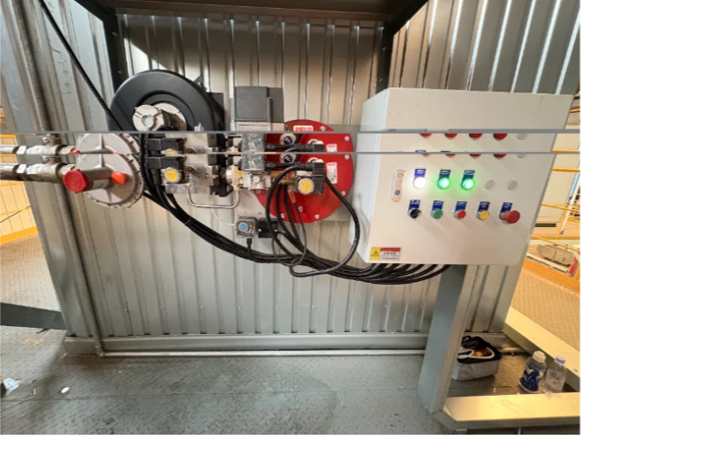
How to Design a Customized Combustion System for Industrial Efficiency
Start with Heat Demand, Not Burner Size
A customized combustion system should be sized from at least three heat-demand points: minimum load, normal load, and peak load. Before a burner model is selected, the design basis should define at least six variables: fuel input, process temperature, temperature tolerance, chamber pressure, draft condition, and required ramp rate.
For boilers, furnaces, kilns, dryers, thermal-oil heaters, and heat-treatment lines, the first engineering task is to map the actual thermal load profile. A burner that only matches the nameplate maximum may cycle excessively at low load, causing unstable O2, higher CO risk, and avoidable purge losses. A practical specification should therefore include hourly load variation, start-up frequency, chamber pressure, draft condition, heat-transfer surface condition, and required ramp rate.
Key indicators to confirm at this stage include:
- Rated heat input: Express the required duty in kW, MW, MMBtu/h, or kcal/h.
- Minimum stable process load: State the lowest stable load as a percentage of full load.
- Temperature tolerance: Define requirements such as +/-1 C for precision heat treatment or a wider range for drying.
- Fuel condition: Confirm available fuel pressure and expected fuel composition variation.
- Stack target: Specify maximum allowable stack temperature or target stack-temperature reduction.
Set Combustion-Air Targets with O2 and CO Together
For many well-designed natural-gas systems, about 10% excess air is attainable, and this commonly corresponds to roughly 2-3% oxygen in dry flue gas depending on fuel and measurement basis [1]. Reducing excess air by 15 percentage points, or reducing stack temperature by 40 F under comparable conditions, is often associated with about 1 percentage point boiler-efficiency improvement [1].
The target is not simply “lower oxygen.” Too little air can create CO, soot, flame impingement, delayed ignition, or unstable flame detection. Too much air increases flue-gas mass flow, carries more sensible heat to the stack, reduces flame temperature in some zones, and can reduce fuel-to-load efficiency. A customized combustion system should use O2 trim, CO monitoring, VFD combustion-air control, or a calibrated air-fuel ratio curve when the process load changes often.
- Multi-point tuning: Tune at low, mid, and high fire instead of relying on a single high-fire adjustment.
- Measured gases: Record O2, CO, CO2, NOx, stack temperature, draft, and fuel pressure at each point.
- CO margin: Keep a CO safety margin defined by the burner OEM, insurer, local code, and plant permit.
- Retuning trigger: Recheck tuning after fuel-gas composition, refractory condition, or process loading changes.
Match Turndown Ratio to Real Process Load
An 8:1 to 12:1 burner turndown ratio is often more useful than a larger burner capacity when the plant spends many hours below full load. If the minimum stable firing rate is too high, cycling losses and temperature overshoot can offset the efficiency benefit of a high peak-capacity burner.
Turndown ratio links directly to industrial efficiency because it determines whether the system can stay in controlled modulation rather than repeated purge, ignition, and shutdown sequences. For a dryer with variable moisture content, a furnace with batch loading, or a boiler serving changing steam demand, the design should calculate the lowest stable heat release that still maintains flame signal, burner pressure drop, and safe chamber conditions.
For B2B procurement, the specification should request documented turndown at the intended fuel type, chamber pressure, and emissions configuration. A 10:1 claim without the fuel pressure range, burner head configuration, fan curve, and control-valve authority is not enough for engineering acceptance.
Control NOx Without Creating a CO or Stability Problem
EU Directive 2015/2193 lists a 100 mg/Nm3 NOx limit for new natural-gas medium combustion plants other than engines and gas turbines, using the directive’s stated reference conditions [2]. Low-NOx burners and flue gas recirculation can reduce thermal NOx, but the final guarantee depends on burner geometry, furnace temperature, residence time, oxygen level, fuel nitrogen, and local permit basis [3].
NOx control is a balance of flame temperature, oxygen availability, mixing intensity, and residence time. Flue gas recirculation in the 10-20% range is a common engineering discussion point for gas-fired industrial boiler applications, and EPA technical material documents NOx dependence on recirculated flue-gas percentage in industrial boiler tests [3]. However, adding FGR can reduce flame speed, change ignition behavior, and require a different burner head, fan capacity, control valve, and flame scanner arrangement.
- NOx target: State units, oxygen reference basis, dry/wet basis, and jurisdiction.
- Operating window: Define expected operating O2 window and CO limit.
- Control method: Identify whether FGR, staged air, low-NOx burner head, or SCR is included.
- Acceptance basis: Define the test method and load points.
- Guarantee limits: List site conditions that void or change the emissions guarantee.
Use Controls That Hold Efficiency Across the Load Range
A modern customized combustion system should be verified at no fewer than three firing positions: low fire, mid fire, and high fire. At each point, the control system should record at least four efficiency-related values: O2, CO, stack temperature, and firing rate, because the EPA boiler tune-up guide links stack loss to flue-gas temperature and combustion conditions [4].
The control architecture should be selected according to risk and process value. A simple jackshaft linkage may be acceptable for stable, low-variation service. Parallel positioning, VFD fan control, pressure compensation, O2 trim, and PLC-based sequencing become more important when fuel pressure changes, ambient air temperature varies, or the process requires tight temperature uniformity.
- Combustion curve: Include a combustion curve table for each fuel.
- Commissioning records: Store low-fire, mid-fire, and high-fire commissioning data.
- Alarm thresholds: Define high CO, low air pressure, flame failure, gas pressure deviation, and purge fault alarms.
- Trend data: Log O2, stack temperature, firing rate, and trip history.
- Authorization: Define manual override rules and authorization level for parameter changes.
Build Safety Into the Mechanical and Electrical Design
Combustion safety acceptance should include at least six functional checks: purge, flame failure, low gas pressure, high gas pressure, combustion-air proving, and emergency stop logic. Public NFPA 86 training summaries state that safety shutoff valve leakage testing frequency is at least annually, but the enforceable requirement must be confirmed from the adopted edition and local authority having jurisdiction [5].
A combustion system is not efficient if it sacrifices safe ignition, purge, flame supervision, or fuel isolation. The fuel train, burner management system, purge-air calculation, flame scanner, pressure switches, and emergency stop logic must be engineered as one package. For ovens and furnaces, combustion-safety standards often drive valve arrangement, proof-of-closure logic, purge timing, and interlock testing.
- Purge: Verify pre-purge and post-purge operation.
- Gas pressure: Test low and high gas-pressure switches.
- Air proving: Test combustion-air proving logic.
- Flame failure: Confirm flame failure response.
- Fuel isolation: Perform safety shutoff valve leak tests.
- Restart logic: Test emergency stop and restart logic.
Specify the Acceptance Test Before Buying Equipment
An acceptance test should cover at least three load points: low fire, normal operating load, and high fire. Each point should record O2, CO, NOx, stack temperature, draft, fuel pressure, air pressure, firing rate, process temperature, and visible flame condition.
This prevents a common procurement problem: the buyer receives a burner that meets capacity but not the plant’s efficiency, emissions, or controllability goals. A customized combustion system should be purchased against measurable outcomes, not only brand, burner size, or price. The contract should state the fuel, site altitude, ambient temperature range, chamber backpressure, reference oxygen basis for NOx, and whether the test is factory, cold-site, hot-site, or third-party witnessed.
- Efficiency: State the target or verified stack-loss reduction.
- O2 range: Use a range such as 2-3% for many gas-fired boiler tuning cases when CO and stability remain acceptable.
- CO threshold: Define maximum CO by permit, OEM, or safety policy.
- NOx limit: State mg/Nm3 or ppm with oxygen basis.
- Temperature: Define temperature-control tolerance and recovery time.
- Turndown: Verify turndown ratio and minimum stable firing rate.
- Safety: Record safety interlock response times and test intervals.
Frequently Asked Questions (FAQ)
REFERENCES AND DATA SOURCES:
- U.S. Department of Energy, “Improve Your Boiler’s Combustion Efficiency,” Energy Tips: Steam, including 10% excess-air attainability for well-designed natural-gas systems and the 1% efficiency rule of thumb for 15% excess-air or 40 F stack-temperature reduction.
- European Union, Directive (EU) 2015/2193 on the limitation of emissions of certain pollutants into the air from medium combustion plants, Annex II emission limit values for new medium combustion plants.
- U.S. Environmental Protection Agency, “Reference Guideline for Industrial Boiler Manufacturers to Control Pollution with Combustion Modification”, EPA technical discussion of flue gas recirculation and NOx behavior in industrial boilers.
- U.S. Environmental Protection Agency, “Boiler Tune-up Guide”, discussion of stack loss, flue-gas temperature, and excess-air effects during boiler tuning.
- Rockford Systems, “NFPA 86 Training and Testing Requirements”, public summary citing at least annual testing frequency for safety shutoff valve leakage testing; confirm enforceable requirements against the adopted NFPA edition and authority having jurisdiction.