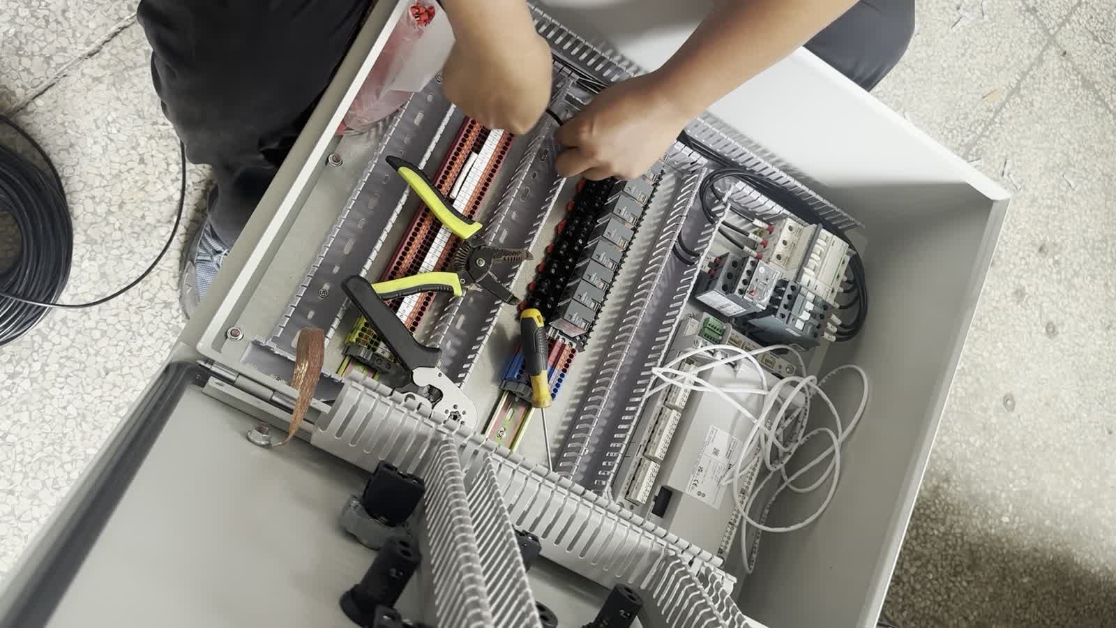
A burner control panel is not a generic electrical box assembled around a standard parts list. It is the electrical interface between the burner, fuel train, combustion-air equipment, flame safeguard, process controller, and the plant’s operating system. Its configuration therefore follows the fuel, burner capacity, process temperature, control philosophy, site power, field instruments, and safety requirements of the application.
The short video below shows a Heatflam engineer wiring a project-based control cabinet. It documents real terminal, cable, and control-component work; it does not represent a completed compliance test or commissioning result.
What Does a Burner Control Panel Control?
At cabinet level, an industrial control panel is an assembly of power and/or control-circuit components. Common panel components include switches, terminal blocks, contactors, drives, transformers, and overcurrent protection devices.[1] A combustion control panel adds the interfaces needed to supervise burner start-up, flame establishment, firing operation, shutdown, and fault response.
Depending on the project, the cabinet connects some or all of the following:
- Power and protection: incoming supply, disconnecting means, circuit protection, control transformer or DC power supply, and protective bonding.
- Combustion-air equipment: fan starter or variable-frequency drive, damper actuator, airflow or air-pressure switch, and position feedback.
- Fuel-train equipment: safety shutoff valves, pressure switches, valve proving equipment when specified, regulators with electrical feedback where applicable, and fuel-selection circuits for dual-fuel systems.
- Ignition and flame supervision: ignition transformer, pilot or main-valve commands, flame detector, and burner control or flame safeguard.
- Process and plant interfaces: temperature or pressure demand, modulation command, run and fault status, emergency-stop chain, remote permissives, PLC/HMI signals, and industrial communications.
What Must Be Defined Before Burner Control Panel Wiring Starts?
Wiring begins after the engineering inputs have been translated into a schematic, component schedule, I/O list, terminal plan, and cabinet layout. IEC 60204-1 covers electrical, electronic, and programmable electronic equipment for machinery from the point where the machine’s electrical supply is connected, and it addresses subjects including overcurrent protection, protective bonding, control circuits, emergency stop, EMC, and technical documentation.[2]
The engineering team should define these inputs before cabinet assembly:
- Fuel type, available fuel pressure, burner model, heat-output range, turndown requirement, and single- or dual-fuel operation.
- Supply voltage and frequency, control voltage, motor ratings, fault-current information, and site earthing arrangement.
- Required operating sequence, permissives, trips, alarm reset philosophy, local/remote selection, and plant DCS or PLC interface.
- Flame detector type, ignition method, air and fuel pressure supervision, valve feedback, process limit switches, and temperature or pressure instruments.
- Installation environment, enclosure requirement, cable-entry direction, available space, ambient conditions, hazardous-area classification where relevant, and the governing local code.
How Is a Custom Burner Control Cabinet Laid Out?
A clear internal layout gives installers room to route conductors, inspect terminals, replace serviceable components, and trace signals against the drawing. The arrangement also needs to respect component instructions, electrical spacing, heat dissipation, cable bend radius, electromagnetic compatibility, and separation between circuit groups. OSHA’s general electrical requirements identify wire-bending and connection space, insulation, heating, equipment ratings, environmental suitability, durable marking, and workmanlike installation as safety considerations for electrical equipment.[3]
A practical layout normally groups power protection and motor switching away from low-level detector, analog, and communication wiring. Wire ducts should preserve access to terminal screws and device labels. Field terminals should follow the terminal plan and leave a logical route from cable entry to each connection point. Protective-earth terminals need a direct, identifiable bonding path; their design is not interchangeable with ordinary control terminals.
How Is Burner Control Panel Wiring Completed?
The physical work shown in the video is one part of a controlled engineering process. The exact sequence changes with the design, but the following workflow keeps each connection traceable.
- Confirm the released drawings. Check device tags, terminal numbers, wire numbers, conductor sizes, control voltage, and field cable destinations before cutting wire.
- Install and identify components. Mount protection devices, power supplies, burner controls, relays, contactors, PLC/HMI hardware where specified, terminals, and protective-earth connections according to the layout and manufacturer instructions.
- Route circuit groups. Keep incoming power, motor circuits, ignition wiring, control wiring, flame-detector signals, analog signals, and communications in their assigned paths. Required spacing and shielding depend on the devices, voltage, enclosure, and applicable standard.
- Prepare and terminate conductors. Strip the specified length, fit the correct terminal or ferrule where required, preserve strand integrity, and tighten each connection to the component manufacturer’s stated torque.
- Label both ends. Wire and terminal identification should match the schematic so field technicians can trace a command, permissive, or feedback signal without relying on wire color alone.
- Inspect against the drawing. Verify terminal location, conductor routing, polarity, protective bonding, unused cores, shield termination, and device settings before power is applied.
| Circuit group | Typical interfaces | Wiring priority |
|---|---|---|
| Power | Incoming supply, fan motor, ignition transformer, heaters | Protection, conductor sizing, isolation, heat, and short-circuit data |
| Safety and permissives | Emergency stop, high limit, air pressure, gas pressure, remote permissive | Defined safe state, supervised logic, clear fault identification |
| Flame and ignition | Flame detector, burner control, ignition and fuel-valve outputs | Manufacturer routing rules, polarity, screening, and separation |
| Process control | Temperature, pressure, modulation, actuator feedback | Signal type, range, reference, shielding, and fail response |
| Plant integration | Run, ready, alarm, reset, demand, PLC/DCS communications | Signal ownership, electrical isolation, protocol, and alarm mapping |
How Are Burner Interlocks and the Operating Sequence Integrated?
The cabinet wiring must implement the approved control philosophy, not create it during assembly. A burner sequence coordinates start permission, combustion-air operation, purge where required, ignition, fuel-valve operation, flame proving, modulation, normal shutdown, and lockout response. The exact sequence and timing come from the burner controller, the burner and fuel-train design, the process, and the governing safety requirements.
NFPA 86 addresses ovens and furnaces, including furnace heating systems, commissioning, operation, maintenance, safety equipment, and application requirements.[4] NFPA 79 addresses industrial machinery electrical equipment and includes requirements for disconnecting means, electrical-hazard protection, equipment protection, marking, documentation, and testing and verification.[5] These standards do not automatically apply to every burner project; the authority having jurisdiction, application type, and contract specification determine the relevant requirements.
Burner-control manufacturer instructions are equally important because detector circuits, safety times, reset behavior, and permitted wiring arrangements are device-specific. For example, Siemens’ LME burner-control documentation lists commissioning checks for flame-detector interruption, simulated loss of flame, air-pressure failure, safety-loop operation, and minimum gas pressure.[6] Those examples illustrate the need to test the selected device according to its own manual; they are not a universal procedure for every controller.
What Is Checked Before the Industrial Burner Control System Operates?
Panel completion and burner commissioning are separate milestones. Before energization, qualified personnel inspect the cabinet against the released drawings and the applicable verification plan. Checks should cover conductor identification, terminal tightness, protective bonding, circuit protection, polarity, separation, device ratings, settings, and the absence of unintended shorts or grounds. OSHA states that completed wiring installations must be free from short circuits and unintended grounds, and that labeled equipment must be installed according to its instructions.[3]
Powered functional checks then confirm input states, output commands, alarms, local/remote control, permissives, and shutdown behavior without bypassing the required safety logic. Live fuel commissioning adds combustion-specific work: leak and valve-train checks under the approved procedure, ignition and flame-signal verification, air/fuel adjustment, limit testing, process response, and documentation of final settings. These tasks require competent personnel, suitable instruments, the burner and controller manuals, and the site’s authorized commissioning procedure.
Why Use a Project-Based Combustion Control Panel?
A project-based panel aligns the cabinet with the actual burner, fuel train, process instruments, plant signals, and installation constraints. It prevents the RFQ from stopping at a list of generic components and gives engineering teams one place to define signal ownership, terminal allocation, operating states, and field interfaces.
Heatflam supports customized burner systems, control cabinets, fuel trains, ignition systems, and project-based integration for industrial heating applications. The scope is configured from the submitted project requirements and confirmed component data. See Heatflam’s industrial combustion solutions for a broader view of the available engineering scope.
What Information Should Be Included in a Burner Control Panel RFQ?
Send enough information to define both the combustion duty and the electrical interface:
- Application and process description; required heat output; operating temperature or pressure range.
- Fuel type, available inlet pressure, burner quantity, burner model if already selected, and required turndown.
- Site voltage, frequency, control voltage, motor data, available fault-current information, and preferred enclosure entry.
- Required local controls, HMI, PLC/DCS signals, communication protocol, alarms, data points, and remote-control philosophy.
- Applicable code or specification, destination country, environmental conditions, hazardous-area classification if any, installation space, and delivery schedule.
- Existing drawings, equipment nameplates, instrument list, fuel-train diagram, and site photographs where available.
Frequently Asked Questions
Send Heatflam your fuel, capacity, process temperature, site voltage, burner and fuel-train information, control requirements, destination country, and applicable project specification.
REFERENCES AND DATA SOURCES:
- UL Solutions — Industrial Control Panels and the Panel Shop Program (Accessed 2026-08-27).
- International Electrotechnical Commission — IEC 60204-1:2016, Safety of Machinery—Electrical Equipment of Machines—Part 1: General Requirements (Published 2016-10-13; consolidated amendment published 2021).
- U.S. Occupational Safety and Health Administration — 29 CFR 1910.303, General Electrical Requirements (Accessed 2026-08-27).
- National Fire Protection Association — NFPA 86: Standard for Ovens and Furnaces (2023 edition).
- National Fire Protection Association — NFPA 79: Electrical Standard for Industrial Machinery (2024 edition).
- Siemens Smart Infrastructure — LME1/LME2/LME4 Gas Burner Controls, Basic Documentation CC1N7101en (Released 2024-03-19).
