Flue gas waste heat recovery systems (also known as exhaust gas heat recovery units) are critical energy-saving devices widely used in industrial settings. Designed to recover residual heat from flue gas emitted by boilers, furnaces, kilns, and other combustion equipment, these systems convert waste thermal energy into usable heat through advanced heat exchange technologies.
As a trusted global provider of industrial combustion solutions, Heatflam integrates waste heat recovery into its end-to-end thermal systems—helping manufacturers achieve 30%+ fuel savings, meet strict emission standards (e.g., EU 50mg/m³ NOx), and enhance production stability. Below is a comprehensive guide to the calculation steps and essential considerations for effective flue gas waste heat recovery, aligned with industrial best practices and global compliance requirements.
1. Data Collection: Lay the Foundation for Precision
Successful waste heat recovery design starts with comprehensive data gathering. Accurate parameters ensure the system integrates seamlessly with your existing combustion equipment (e.g., Low NOx Burners, regenerative combustion systems) and meets your specific industrial needs.
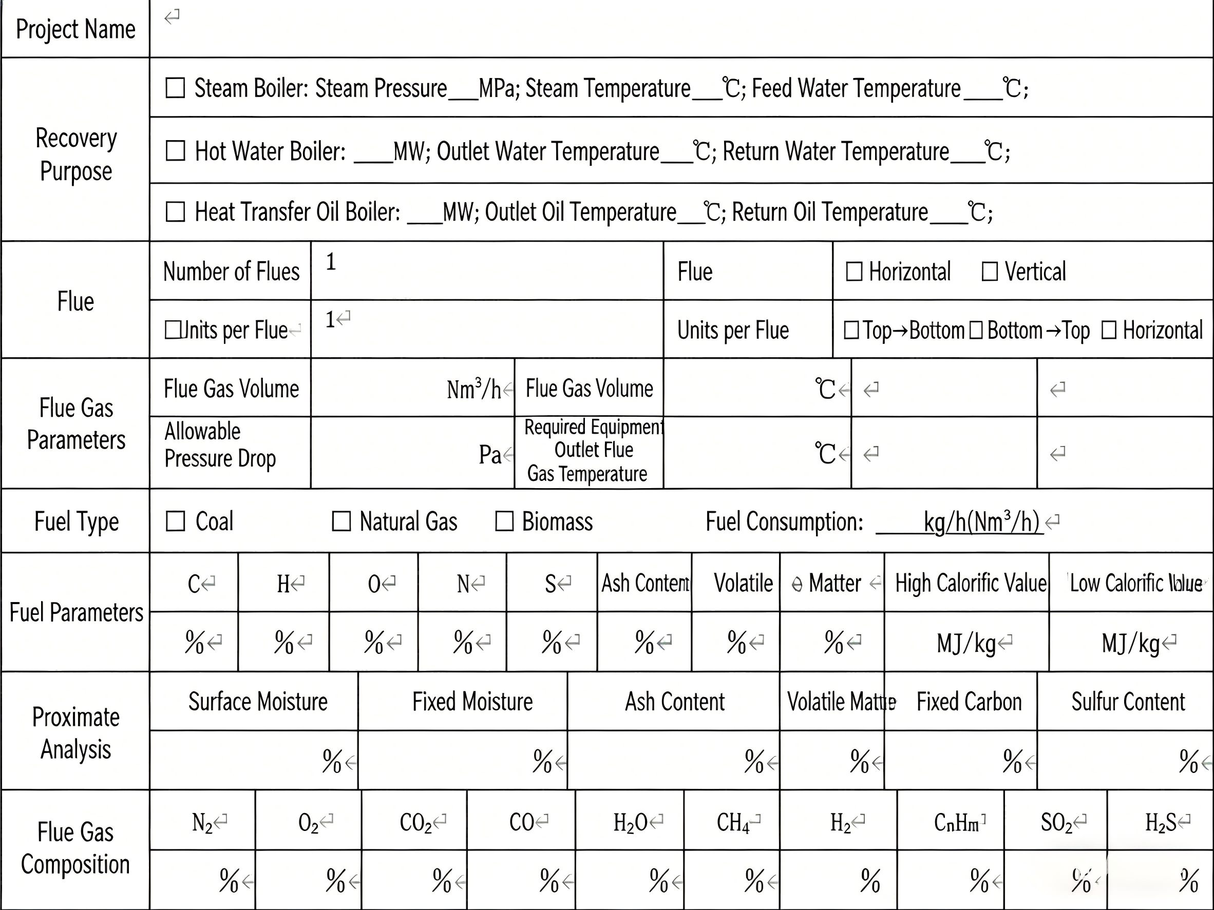
Core Data to Collect:
- Flue gas parameters: Flue gas volume, inlet/outlet temperature, composition (e.g., CO₂, O₂, SOx), and properties (corrosiveness, adhesiveness).
- Working fluid details: Fluid type (water, steam, thermal oil, air), pressure, and temperature requirements.
- Site constraints: Installation space limitations, obstacles, and layout compatibility with skid-mounted systems or existing combustion skids.
Practical Tips for Data Gap Resolution:
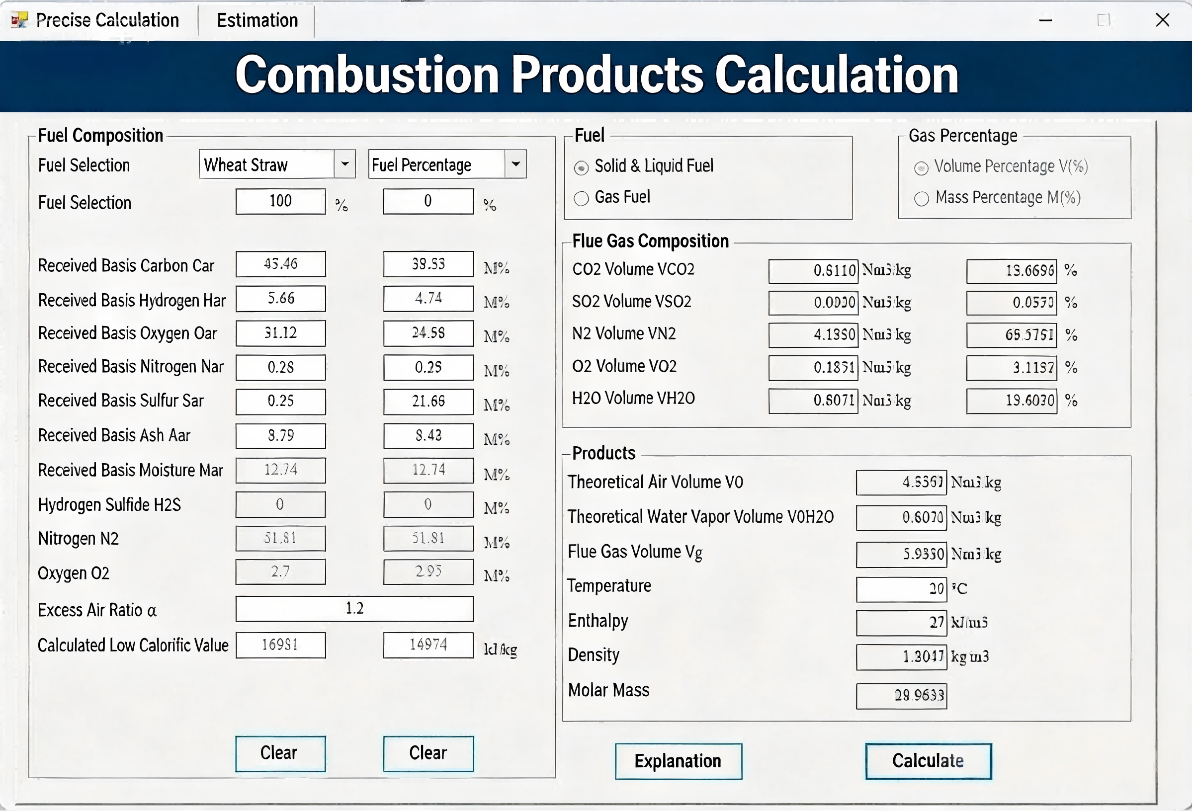
If direct measurements of flue gas volume or composition are unavailable (common in preliminary design phases):
- Calculate flue gas volume and composition using fuel consumption, fuel calorific value, and excess air coefficient.
- Utilize specialized thermal calculation software (recommended for complex fuels like synthetic gas, biomass, or methanol).
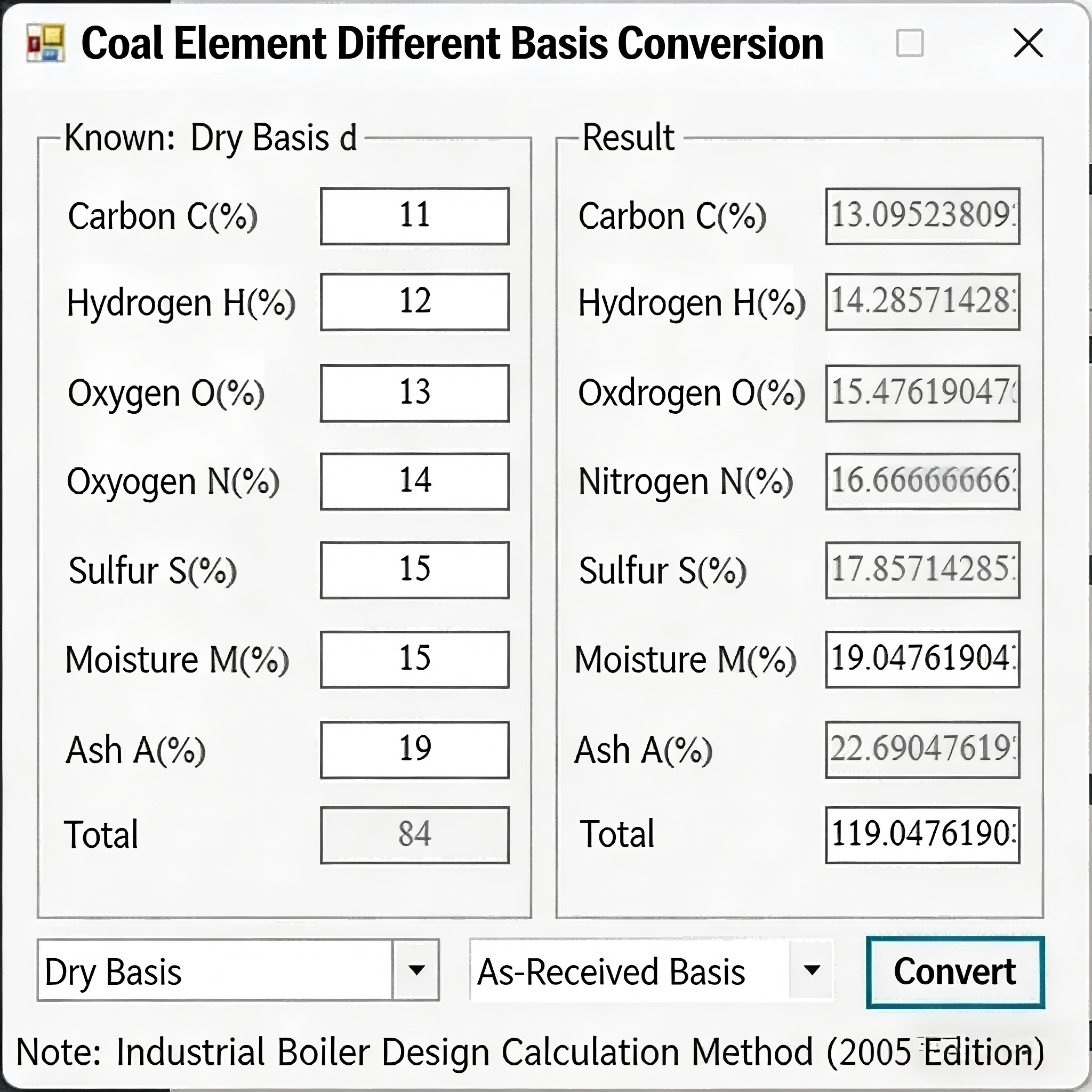
- Convert fuel bases (e.g., from dry basis to as-received basis) using standard formulas referenced in boiler engineering handbooks.
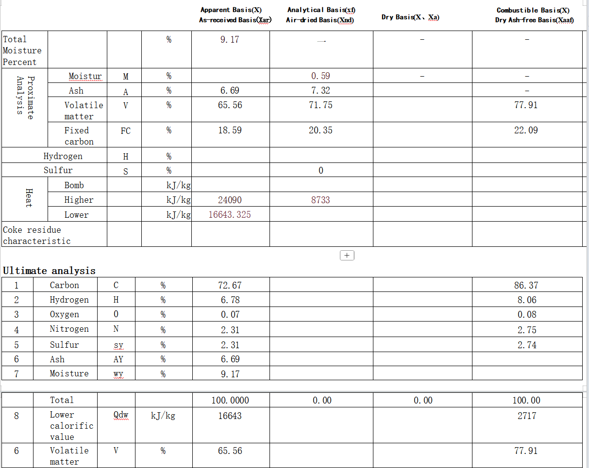
- Estimate elemental composition if only proximate analysis data is provided, following industry-recognized estimation methods.
2. Heat Balance Calculation: Quantify Energy Transfer
Heat balance calculations are fundamental to determining the energy recovery potential of your system. The process relies on six key parameters—five of which must be known to solve for the unknown variable:
- Hot side (flue gas): Flow rate, inlet temperature, outlet temperature
- Cold side (working fluid): Flow rate, inlet temperature, outlet temperature
Core Formulas:
Heat released by flue gas (Q_out) = Hot side flow rate × (Inlet enthalpy – Outlet enthalpy)
Heat absorbed by working fluid (Q_in) = Cold side flow rate × (Outlet enthalpy – Inlet enthalpy)
Enthalpy Calculation Methods by Medium:
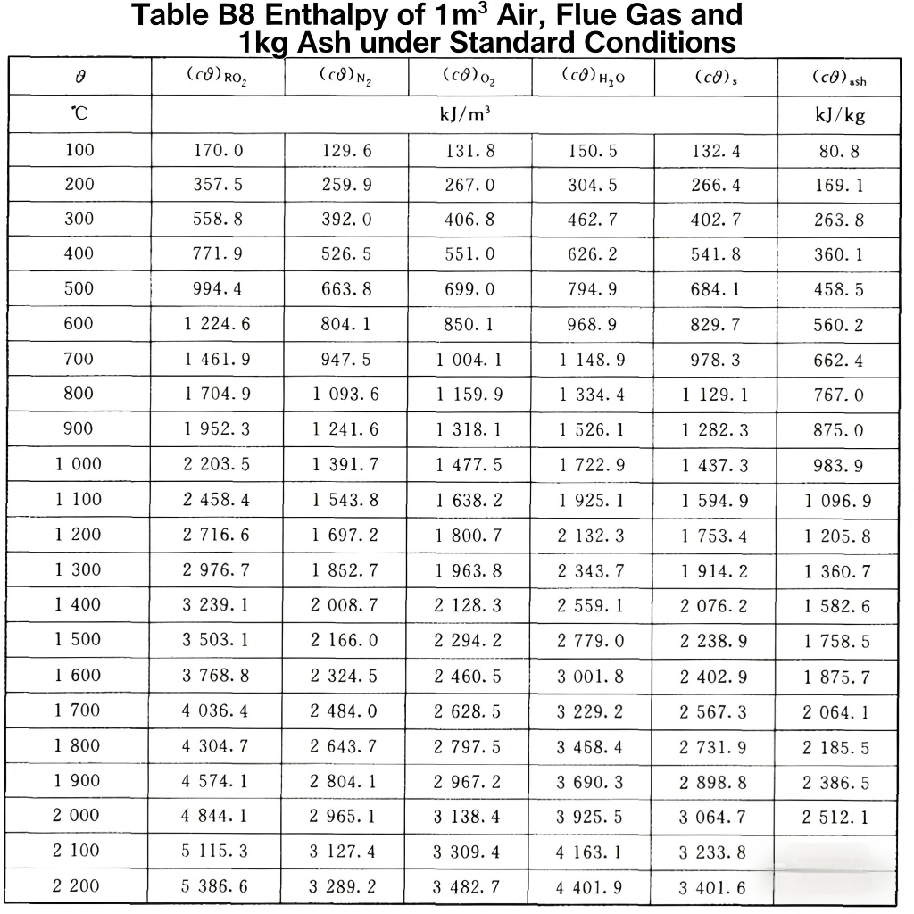
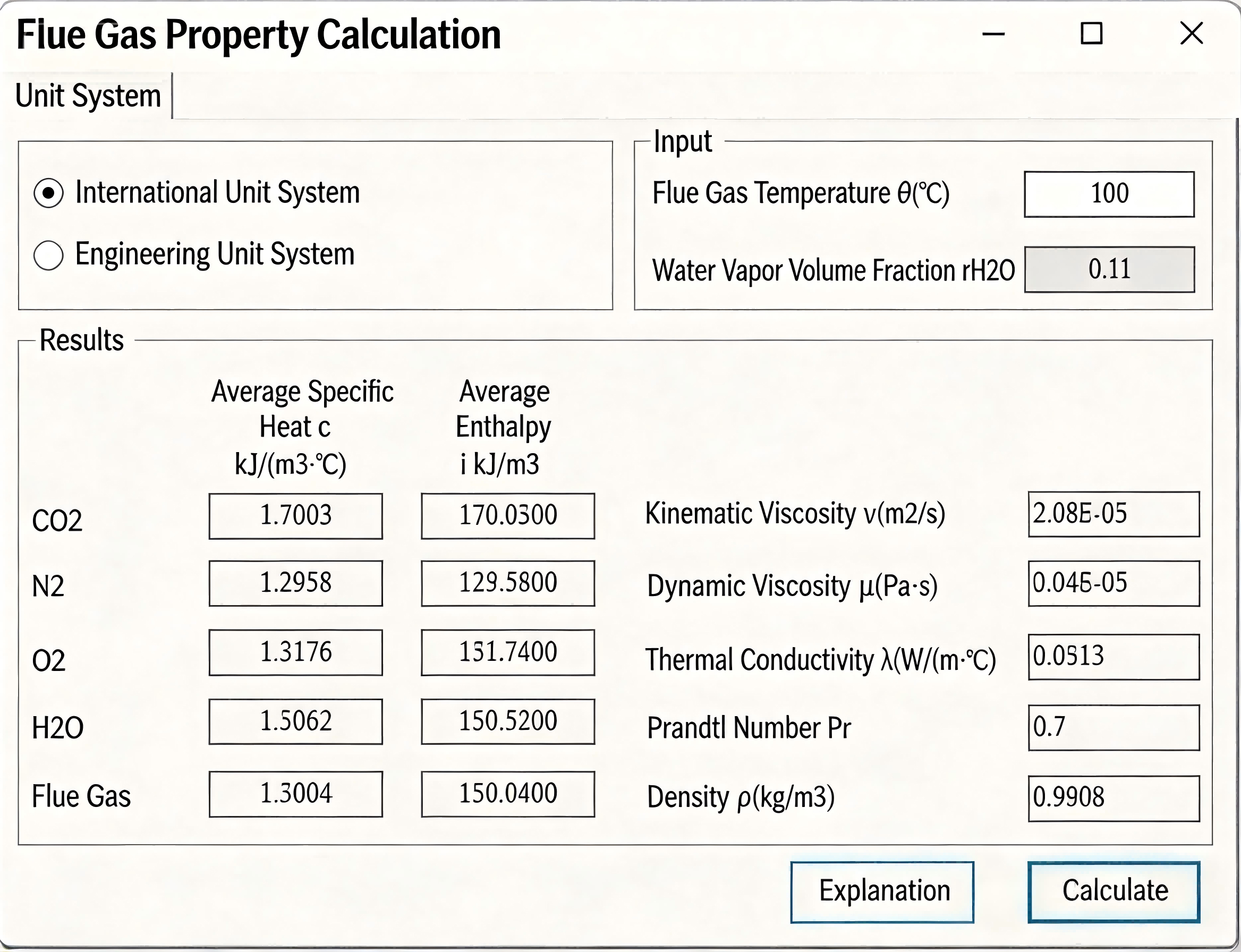
Flue Gas Enthalpy:
- Known composition: Enthalpy = Σ (Volume ratio of flue gas component × Enthalpy of component) – reference standard enthalpy tables for gases like CO₂, N₂, O₂, and H₂O.
- Unknown composition: First calculate flue gas composition from fuel properties (gas, diesel, heavy oil, coal, LNG, etc.), then apply the method above.
Water & Steam Enthalpy:
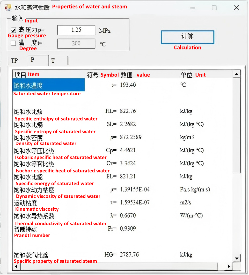
Use steam property tables or specialized thermal calculation software (consistent with Heatflam’s system design workflows for boilers and heating systems).
Air Enthalpy:
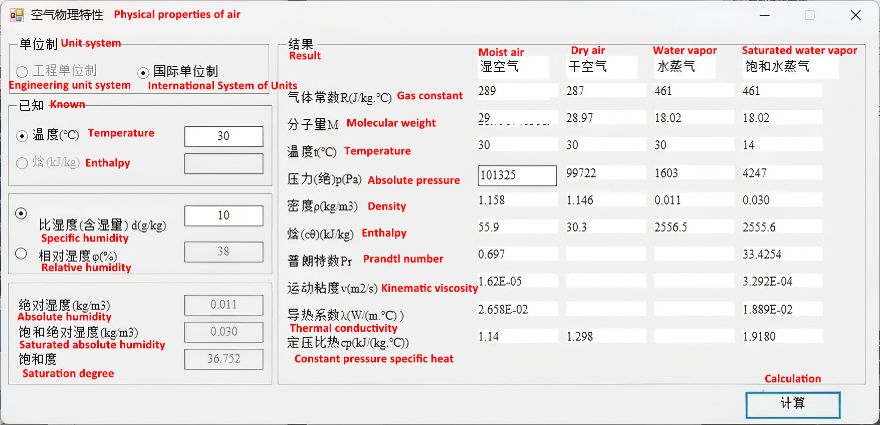
Refer to air property tables or software tools—critical for systems integrating air heating burners or air preheaters.
Thermal Oil Enthalpy:
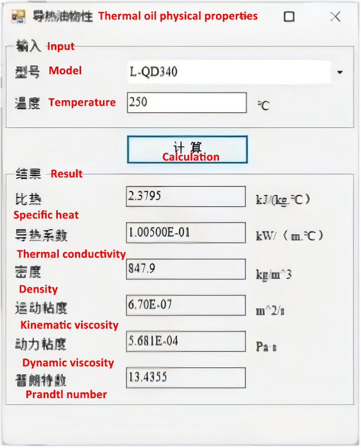
Consult thermal oil property databases or manufacturer specifications, tailored to industrial drying, calcination, or process heating applications.
Mixed Flue Gas Enthalpy:
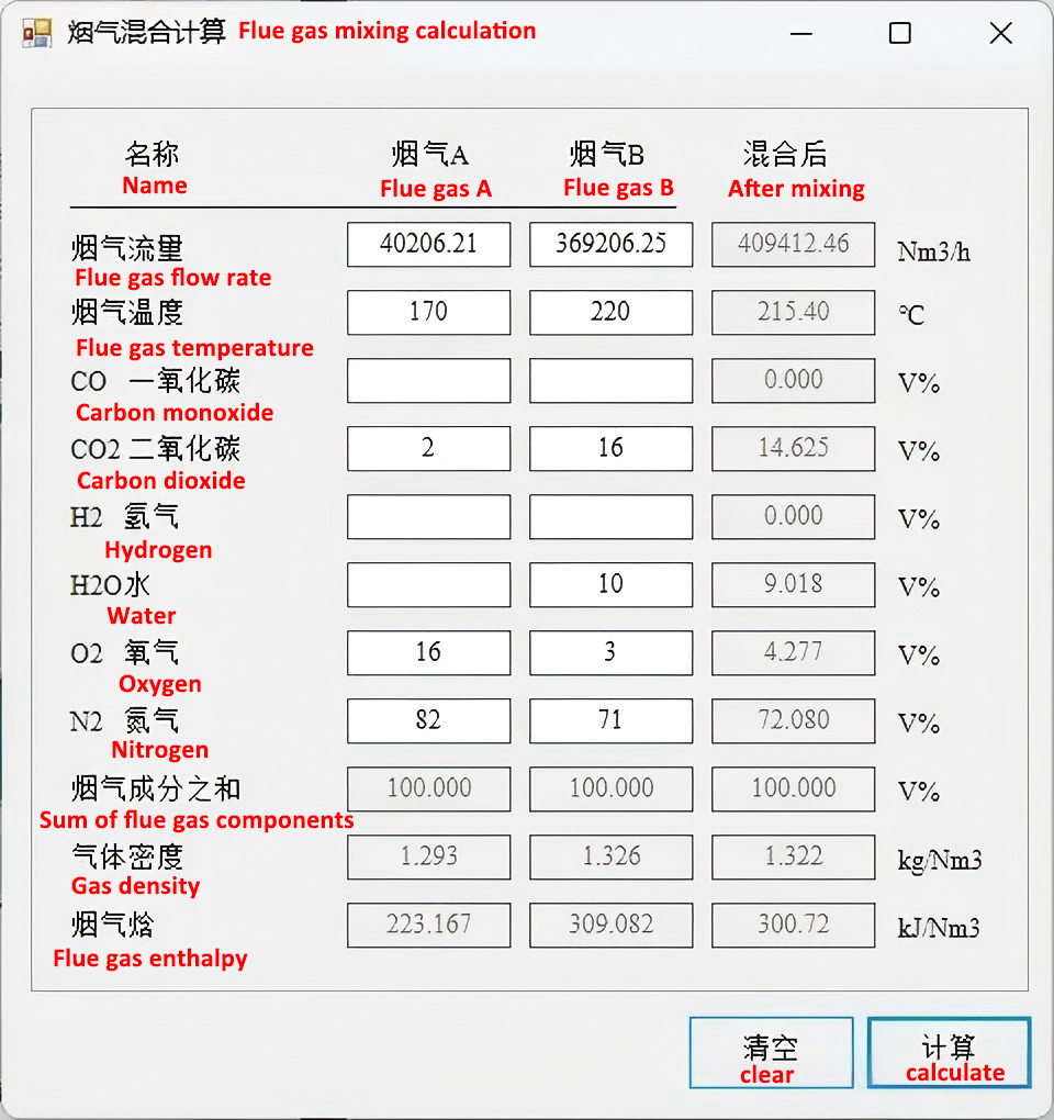
Calculate as the sum of (Volume ratio of each gas × Its enthalpy) for multi-fuel combustion systems (e.g., dual-fuel burners).
3. Temperature Difference (ΔT) Calculation: Optimize Heat Exchange Configuration
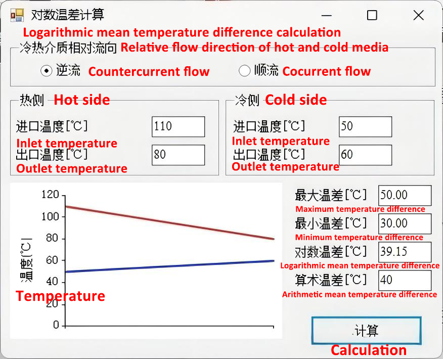
The temperature difference between the hot (flue gas) and cold (working fluid) media depends on their flow direction, which directly impacts heat exchange efficiency. Common flow configurations include countercurrent, concurrent, crossflow, and mixed flow—each suited for different industrial scenarios (e.g., kilns, dryers, marine heating systems).
Key Principles:
- Countercurrent flow: Offers the highest temperature difference (maximizes heat recovery) – ideal for high-efficiency systems like Heatflam’s industrial regenerative combustion solutions.
- Concurrent flow: Provides the lowest temperature difference – used for specific low-temperature applications or to prevent dew point corrosion.
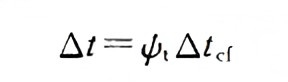
- Crossflow/mixed flow: Temperature difference falls between countercurrent and concurrent; apply a correction factor to countercurrent ΔT for accurate calculations.
Formula for Countercurrent/Concurrent ΔT:

Mean temperature difference
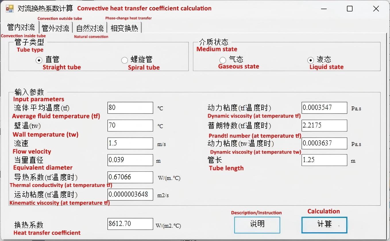
4. Heat Transfer Coefficient (K) Calculation: Account for System Design
The overall heat transfer coefficient (K) quantifies the rate of heat transfer through the exchanger surface, influenced by tube arrangement, flue gas flow direction, and medium properties. This calculation is complex but critical for system performance—especially for high-temperature applications or corrosive flue gases.
Key Factors to Consider:
- Tube arrangement: Staggered vs. in-line tube bundles (affects flue gas flow velocity and heat transfer efficiency).
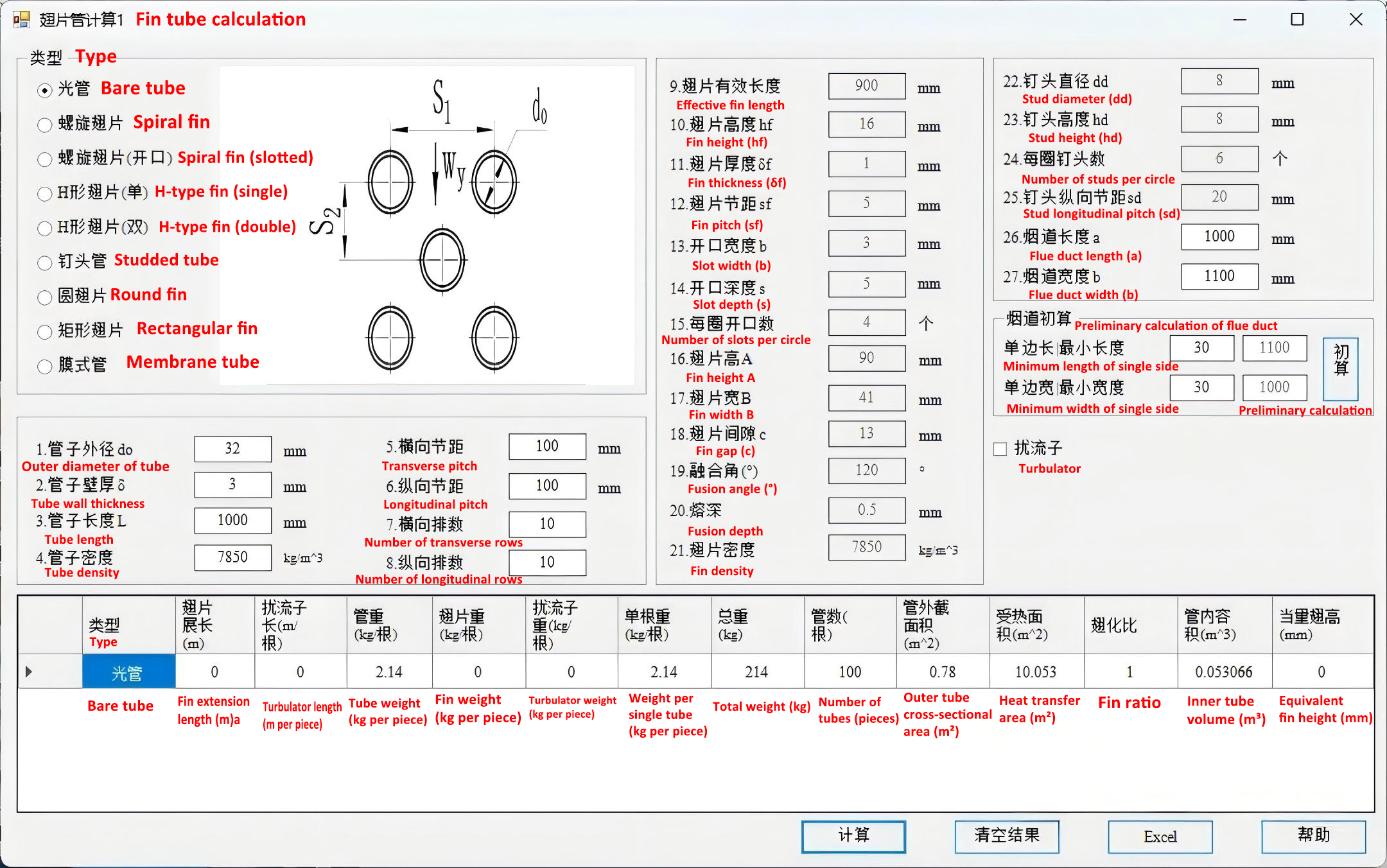
- Tube type: Plain tubes, finned tubes, or studded tubes (Heatflam often uses finned tubes in air preheaters to boost surface area).
- Flow direction: External (crossflow) vs. internal (longitudinal flow) – threaded flue gas tubes require specialized correlations for internal flow.
- Radiation heat transfer: Critical for high-temperature heating surfaces (e.g., in industrial kilns) where triatomic gas (CO₂, H₂O) content is high.
Calculation Approach:
Use industry-standard correlations for convection heat transfer (adjusted for tube type and arrangement) and add radiation heat transfer contributions for high-temperature scenarios. For skid-mounted systems, Heatflam’s engineering team leverages 15+ years of experience to optimize K values for prefabricated solutions.
5. Heat Exchange Area Calculation: Size for Performance
The required heat exchange area depends on the heat transfer coefficient (K), mean temperature difference (ΔTₘ), and heat transfer rate (Q). Different heat exchanger types require specific area calculation methods:
Area Calculation by Exchanger Type:
| Exchanger Type | Calculation Method | Ideal Applications |
|---|---|---|
| Plain Tubes | External surface area (external flow) / Internal surface area (internal flow) | Standard industrial boilers, furnaces |
| Finned Tubes | Total area = Finned surface area + Bare tube area between fins | Air heating, space-constrained systems |
| Studded Tubes | Total area = Stud surface area + Bare tube area between studs | High-corrosion, high-dust environments (e.g., waste incineration) |
| Air Preheaters | Average of internal and external tube surface areas | Metallurgy, chemical processing |
6. Cold Side Heat Absorption Verification: Refine the Design
Verify the calculated heat absorption of the cold side to ensure the system meets energy recovery goals:
Core Formula:
Cold side heat absorption (Q_absorbed) = K × ΔTₘ × Heat exchange area (A)
Iterative Refinement Process:
- Initially assume a heat exchange area based on preliminary calculations.
- Compare Q_absorbed with the heat released by the flue gas (Q_released).
- Adjust the area: Increase if Q_absorbed is insufficient (to meet energy needs) or decrease if oversized (to optimize cost and space).
This iterative approach aligns with Heatflam’s customized design process—ensuring solutions fit exact customer specifications for boilers, furnaces, or waste incineration systems.
7. Key Considerations: Ensure Safety, Compliance, and Longevity
Industrial waste heat recovery systems must address operational risks, regulatory requirements, and environmental standards. Below are critical factors to mitigate issues and maximize system lifespan (consistent with Heatflam’s 10+ year average service life for core systems).
7.1 Prevent Dew Point Corrosion
Flue gas often contains acidic components (e.g., SOx from heavy oil or coal combustion) that cause corrosion when the flue gas temperature drops below the acid dew point.
- Maintain flue gas exhaust temperature above the acid dew point (calculated from fuel or flue gas composition).
- Note: A system-wide flue gas temperature above the dew point does not guarantee protection—focus on the tube wall temperature.
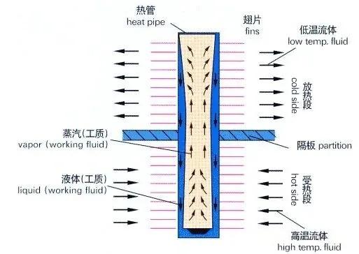
- Mitigation strategies: Use concurrent flow configurations or heat pipe structures (Heatflam’s preferred solution for corrosive environments) to keep wall temperatures above the dew point.

7.2 Explosion Protection for Gas-Gas Systems
For air-air or flue gas-air heat recovery systems (common in chemical, pharmaceutical, or food processing industries):
- Adopt heat pipe structures to fully separate the hot (flue gas) and cold (air) sides.
- This design prevents leakage and potential explosion hazards—aligning with NFPA 85 and local safety regulations.
7.3 Account for Altitude Effects
Standard design assumes sea-level (0 altitude) conditions. For high-altitude installations:
- Air density and thermal properties change, reducing fan efficiency.
- Oversize fans to compensate for altitude-related performance losses—critical for consistent operation in regions like the Middle East or mountainous areas.

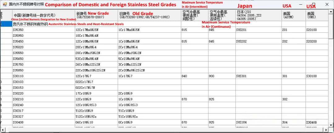
7.4 Material Selection: Balance Performance and Cost
Choose materials based on medium properties, temperature, and corrosion risk—prioritizing cost-effectiveness and compliance:
- Corrosive flue gases (e.g., from waste incineration): Use stainless steel or corrosion-resistant alloys.
- High-temperature applications (e.g., kiln flue gas): Select heat-resistant materials compatible with regenerative combustion systems.
- Standard conditions: Opt for carbon steel to optimize cost—consistent with Heatflam’s quality commitment to using premium components (e.g., Emerson sensors, ASCO valves).
8. Supplementary Calculations: Ensure System Integrity and Compliance
Beyond core heat transfer calculations, the following verifications are mandatory for industrial-grade waste heat recovery systems—aligning with global standards (CE, UL, ISO 9001) and industry-specific requirements (IMO for marine, SCAA for regional emissions):
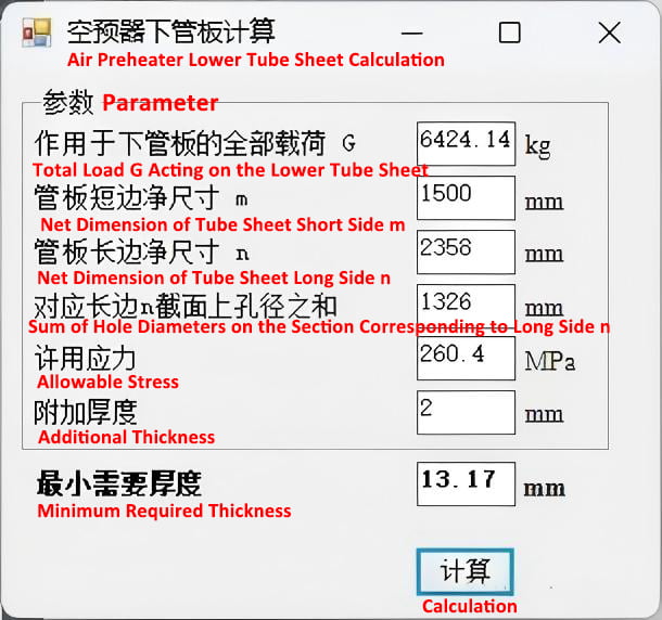
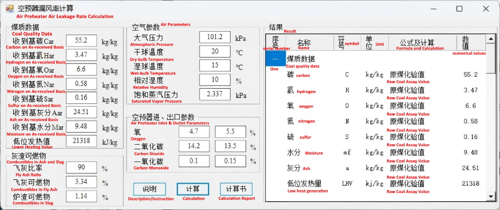
8.1 Air Preheater Tube Sheet Strength Check
For tube-sheet air preheaters, calculate:
- Tube sheet strength to withstand operating pressure and temperature.
- Air leakage rate (critical for maintaining combustion efficiency in industrial burners).
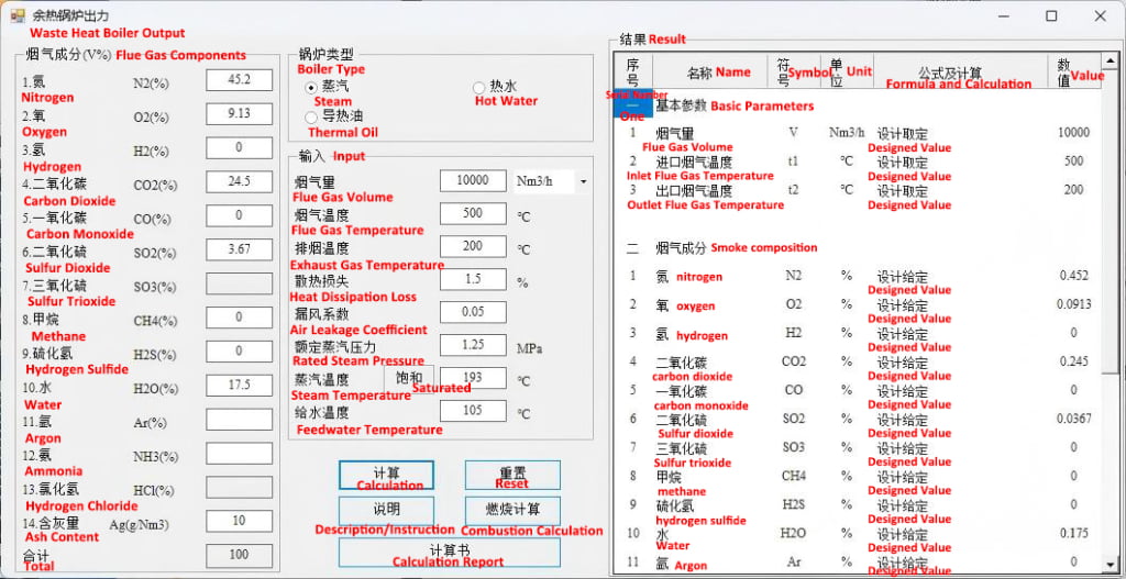
8.2 Waste Heat Boiler Capacity Calculation
Estimate boiler output during preliminary design to align with heating or process steam requirements.
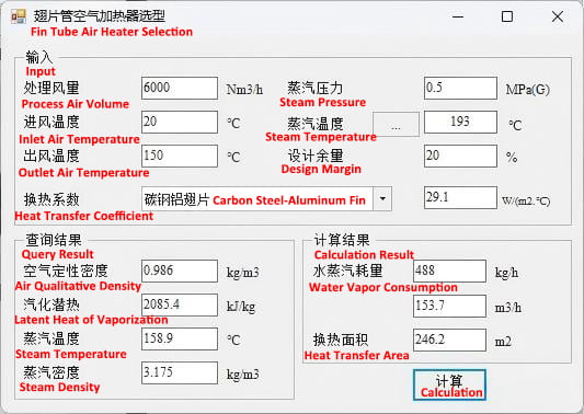
8.3 Finned Air Heater Calculations
Optimize fin spacing, height, and material for air heating applications (e.g., textile drying, food processing).
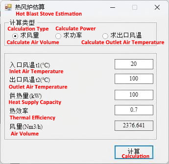
8.4 Hot Blast Stove Calculations
Tailor to metallurgical or industrial heating processes requiring high-temperature air supply.
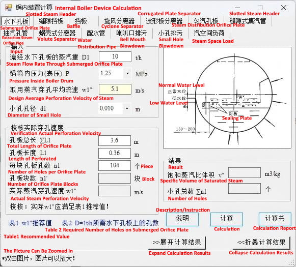
8.5 Boiler Internal Component Design
Calculate or select:
- Primary and secondary steam-water separation devices.
- Blowdown and feedwater pipes—ensuring compliance with boiler safety standards.
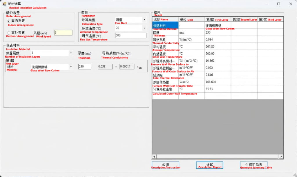
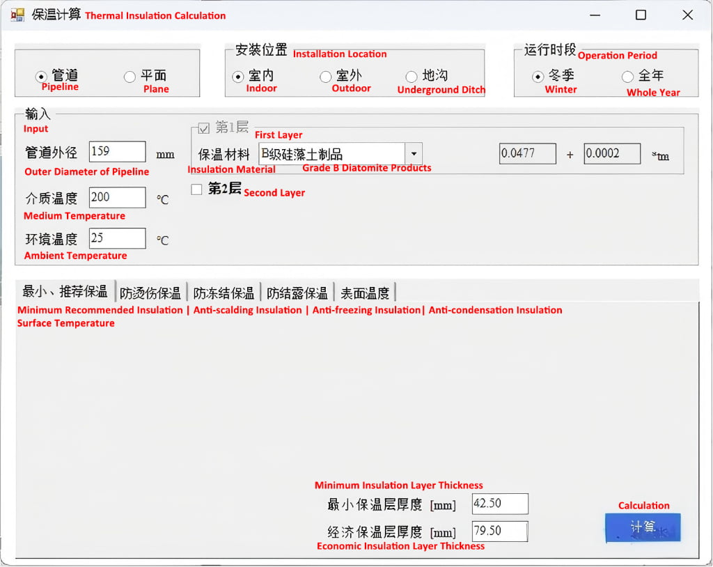
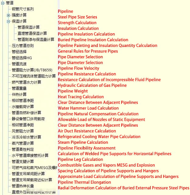
8.6 Insulation Calculations
Design insulation for boilers, pipes, and skid-mounted systems to:
- Limit external surface temperature to ≤50℃ (or ≤ ambient temperature +25℃).
- Minimize heat loss and energy waste—supporting overall energy-saving goals.
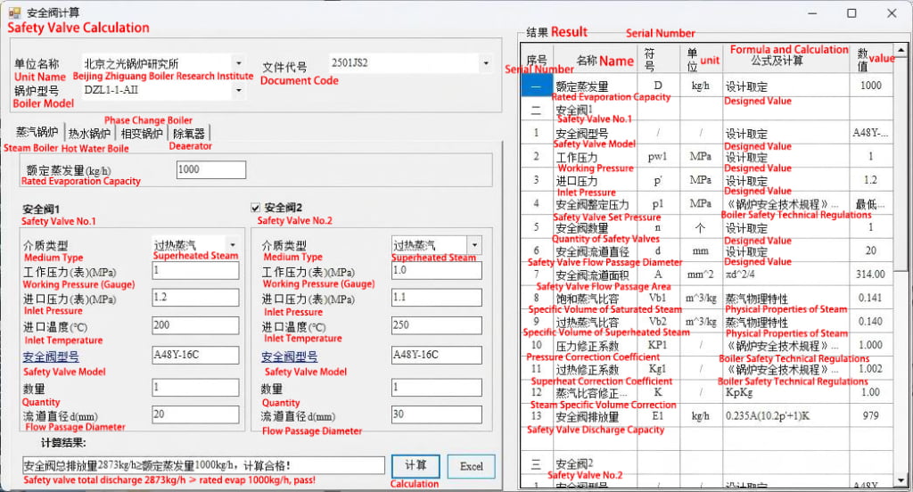
8.7 Safety Valve Verification
As a critical safety component for pressure equipment:
- Verify that the selected safety valve meets required discharge capacity.
- Ensure compliance with global pressure vessel regulations.
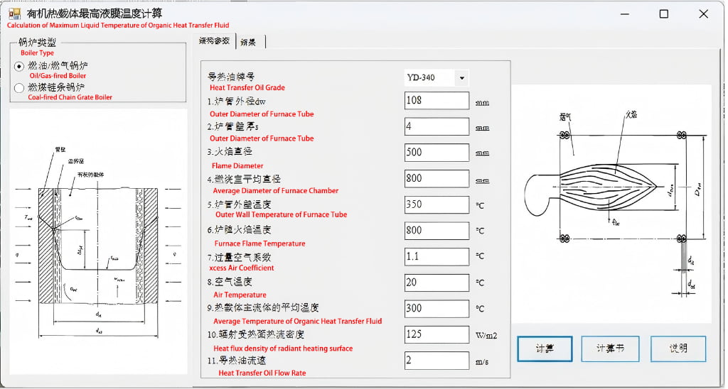
8.8 Maximum Liquid Film Temperature Check
For thermal oil-based systems:
- Calculate the maximum liquid film temperature to prevent thermal oil degradation.
- Align with thermal oil manufacturer’s operating limits.
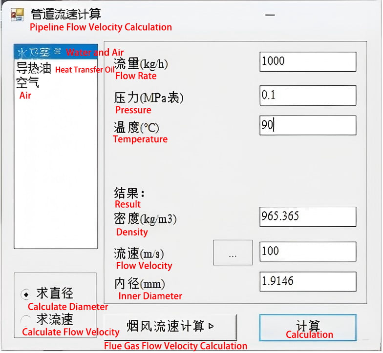
8.9 Tube Velocity Check & Pipe Sizing
- Ensure working fluid velocity meets recommended ranges:
- Avoid undersized pipes (causes excessive system resistance, insufficient pump head, and higher operating costs).
- Avoid oversized pipes (increases equipment costs and reduces heat transfer efficiency).
8.10 Boiler & Piping Strength Calculations
Conduct structural strength checks for all system piping and pressure-containing components—critical for safe operation under industrial conditions.
Partner with Heatflam for Optimized Waste Heat Recovery
Flue gas waste heat recovery is a cornerstone of industrial energy efficiency, but its success depends on precise calculations, compliance with global standards, and seamless integration with your combustion systems.
At Heatflam, we combine 15+ years of industrial combustion expertise with customized design—delivering waste heat recovery solutions tailored to metallurgy, chemical processing, marine, waste treatment, and food processing industries. Our end-to-end services include engineering consultancy, 24/7 multilingual technical support, and skid-mounted solutions that reduce on-site installation time by 40%.
To learn how our Low NOx burners, regenerative combustion systems, and waste heat recovery integrations can help you cut fuel costs, meet emission targets, and enhance production stability, contact us today:
- 📱 WhatsApp: +86 18917086029
- 📧 Email: sun@heatflam.com
- 🏢 Address: Room 301, No. 95 Jianhao Road, Shanghai, China